The Chicken Coop Controller
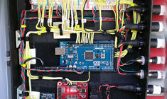
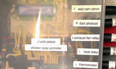
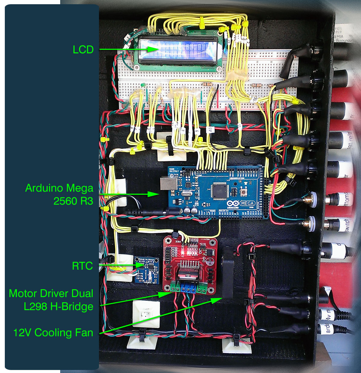
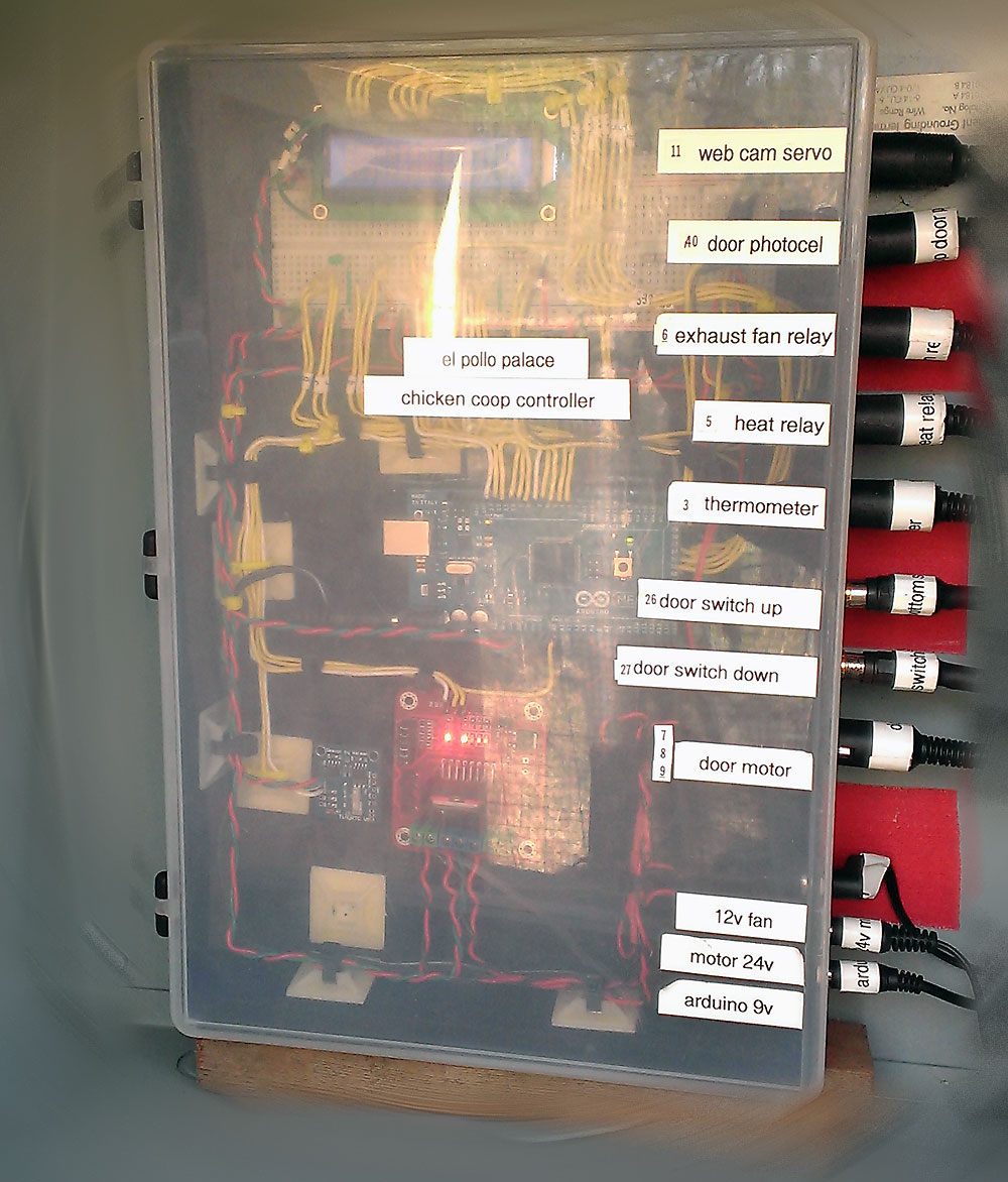
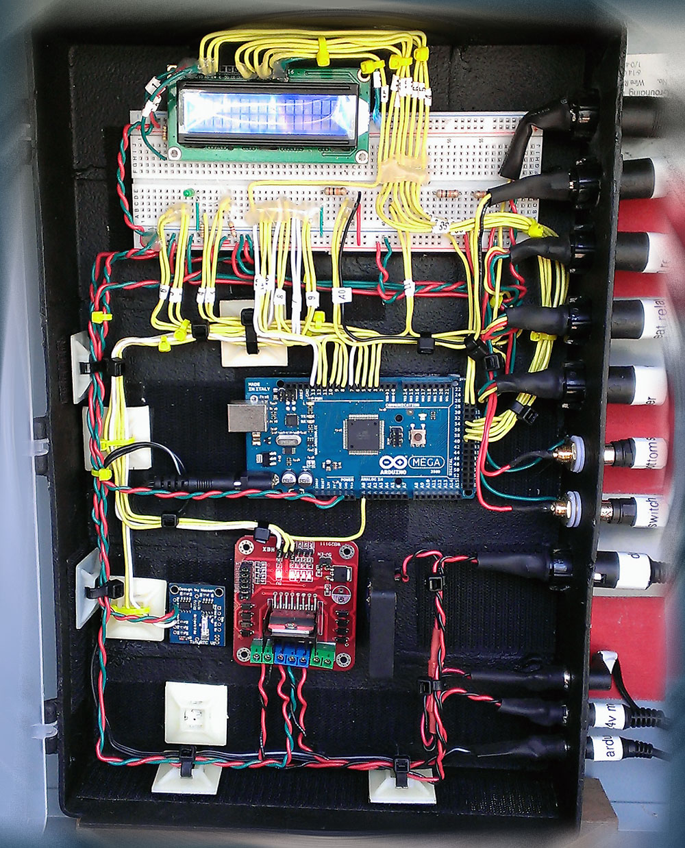
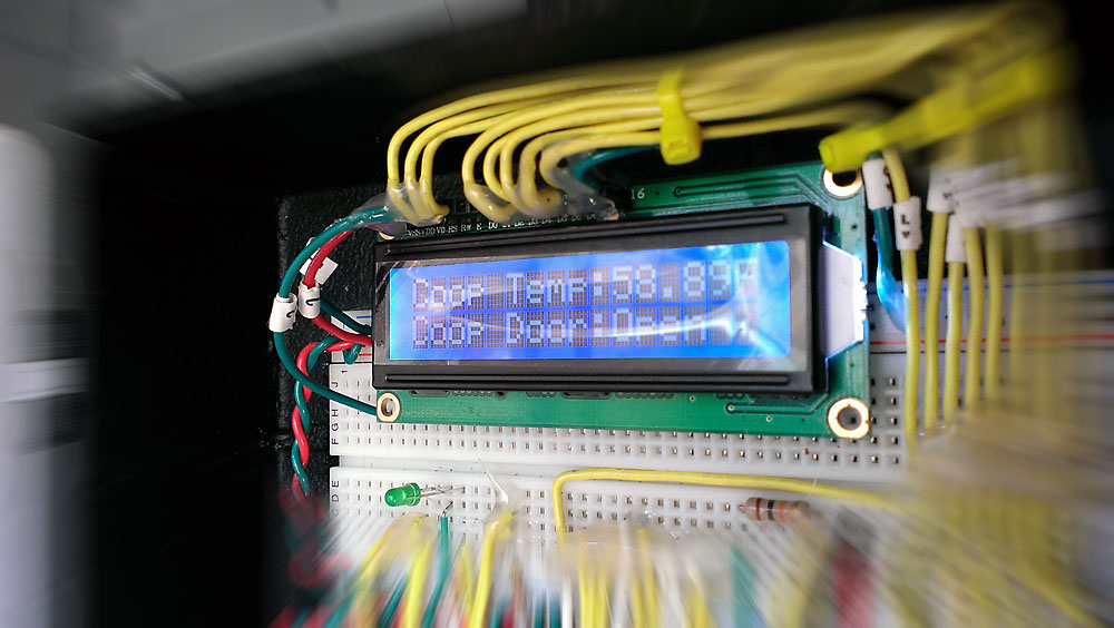
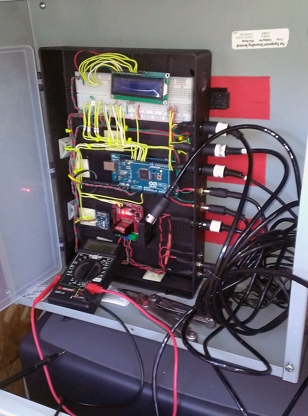
This would be the brains of the entire system, encased in a simple plastic organizer with the dividers removed. It’s set within a UL approved metal electrical housing, which is nestled within the El Pollo Palace Network Operations Center or “E.P.P.N.O.C.” =) When I started the coop, I knew I wanted it to be technically advanced beyond reason, but I didn’t really want it to *look* too high tech, (at least not from the exterior) but not too “country” either. So I just went for it and I’m pretty happy with the results.
Click for details >
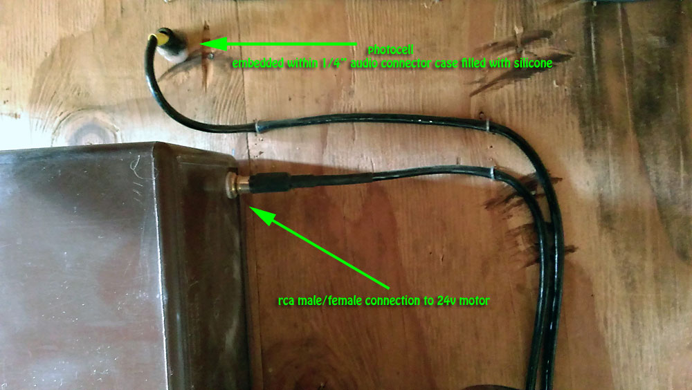
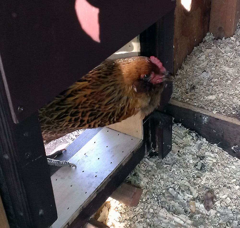
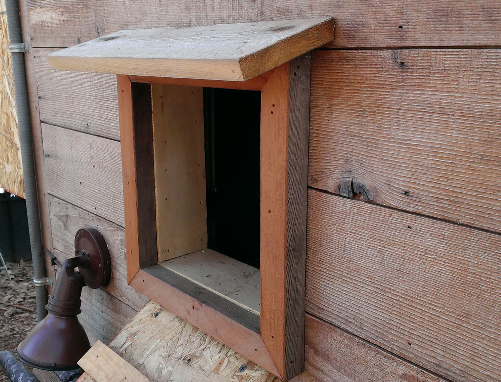
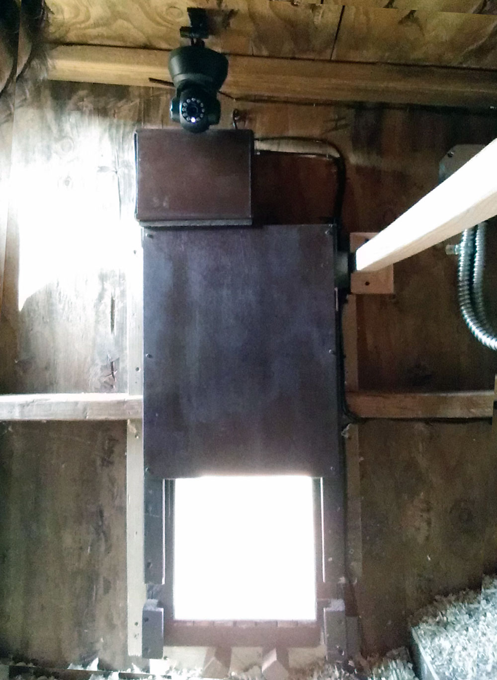
Automatic Chicken Coop Door
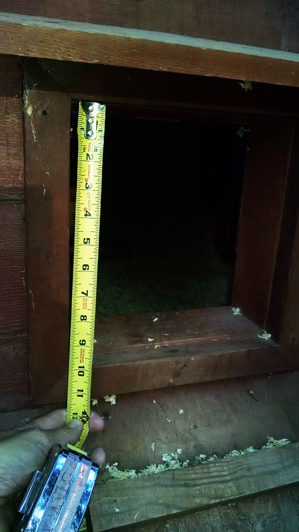
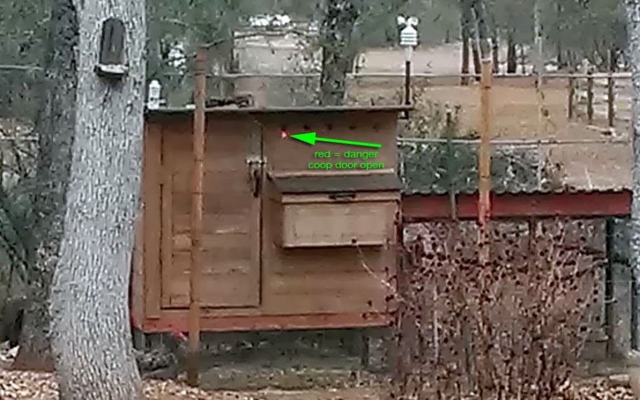
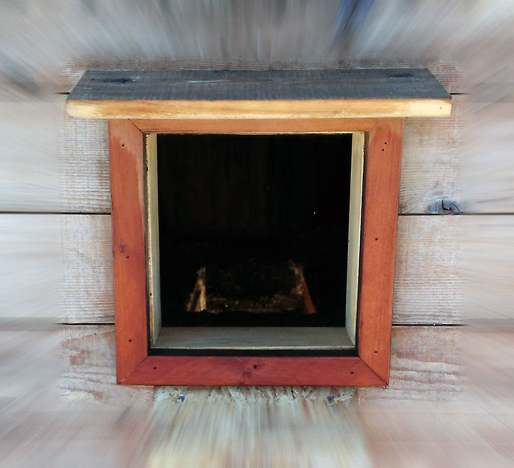
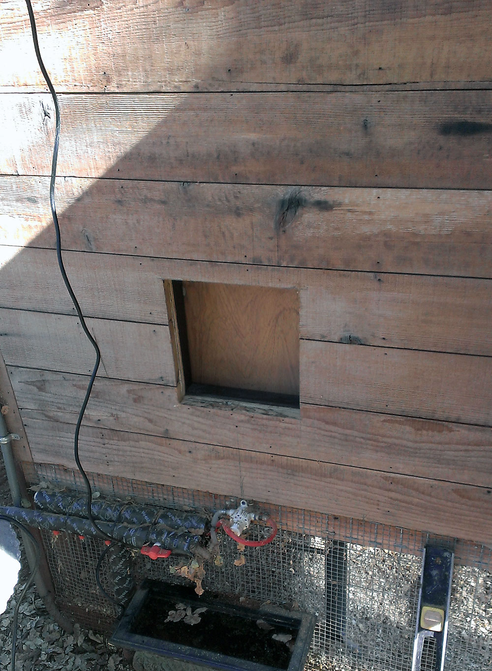
I wanted a small door to open automatically (via Arduino / time of day) to the outside world. Doing this would relieve us from worrying if the chickens were safe at night and to be able to… Click for details >
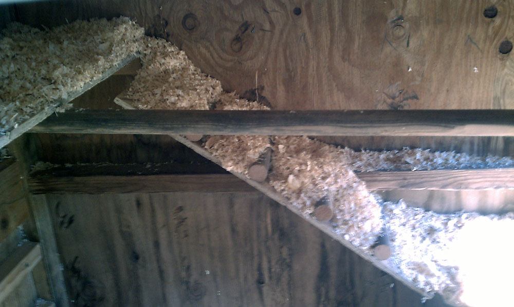
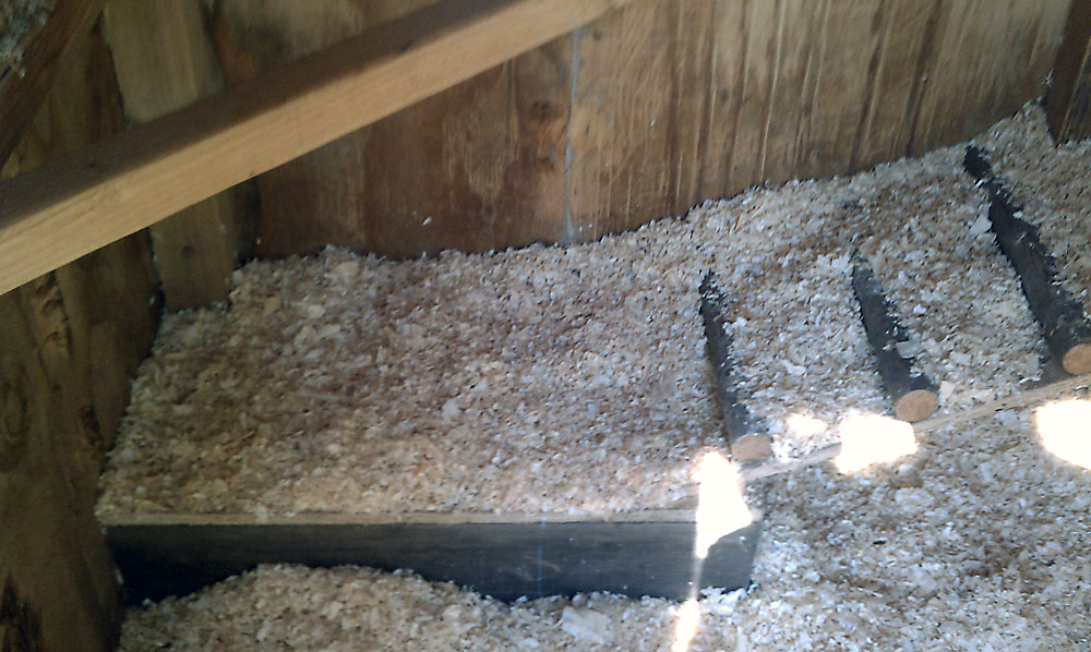
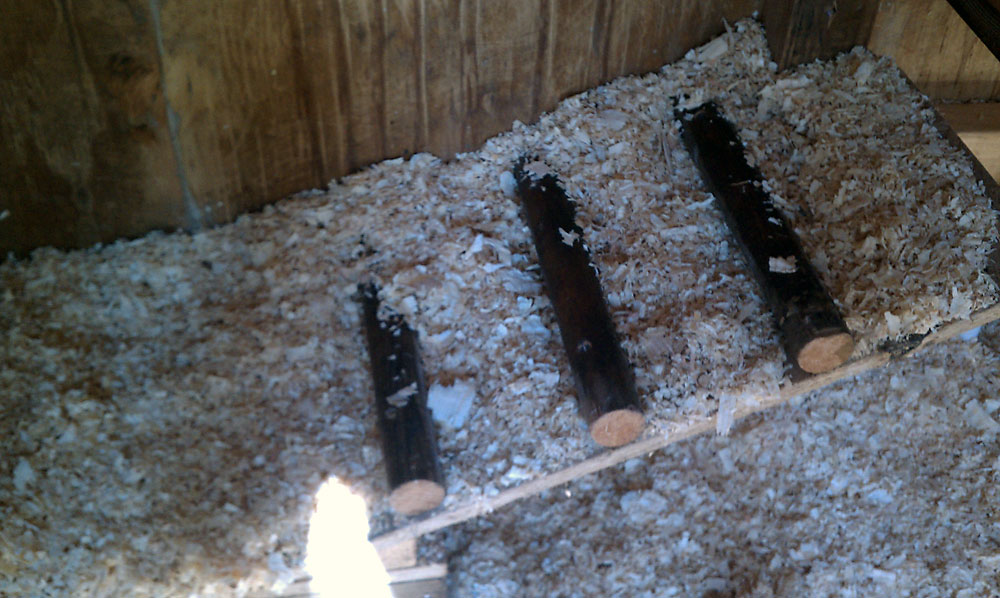
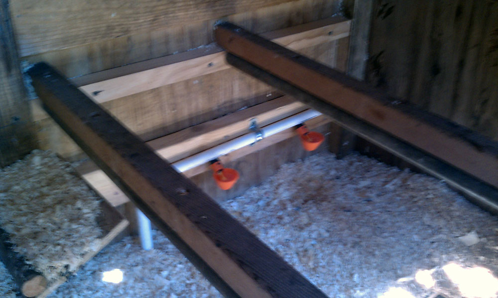
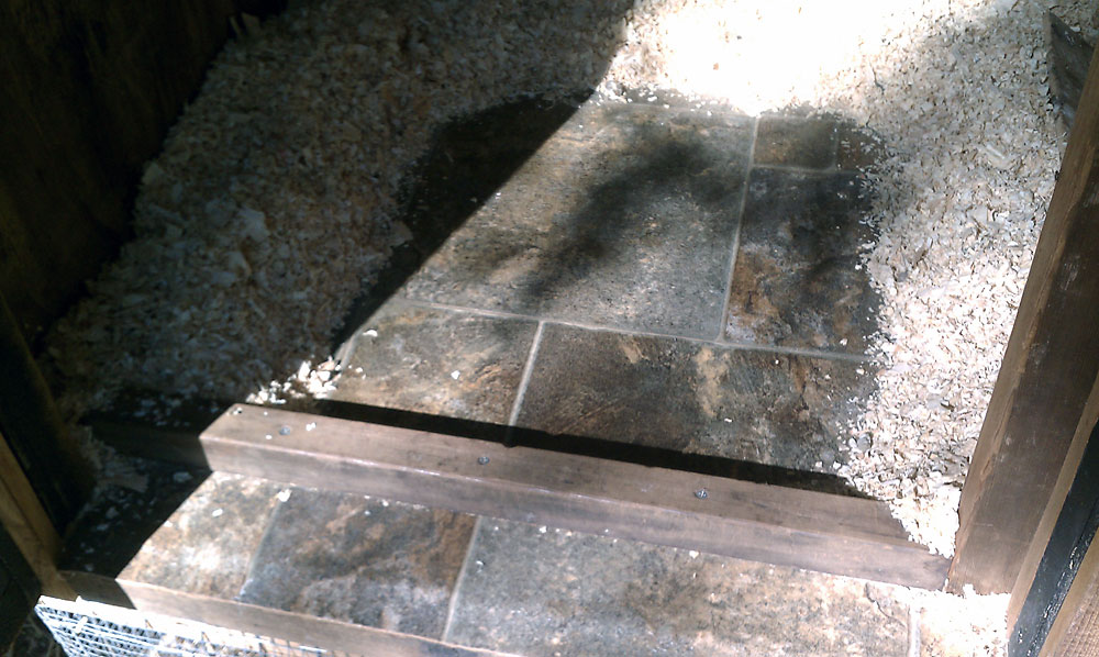
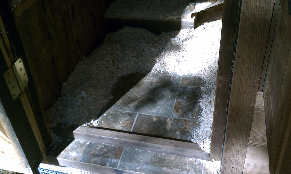
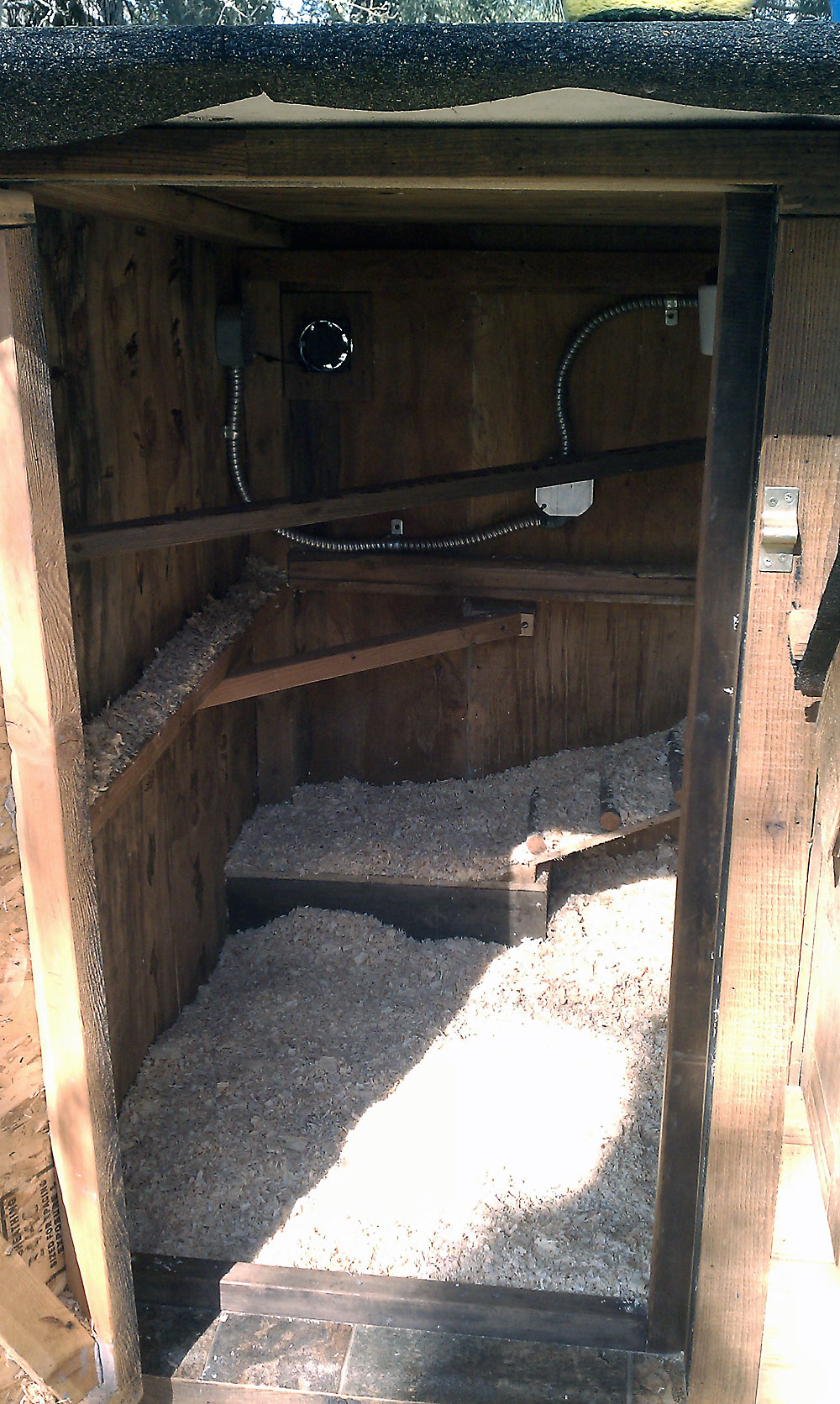
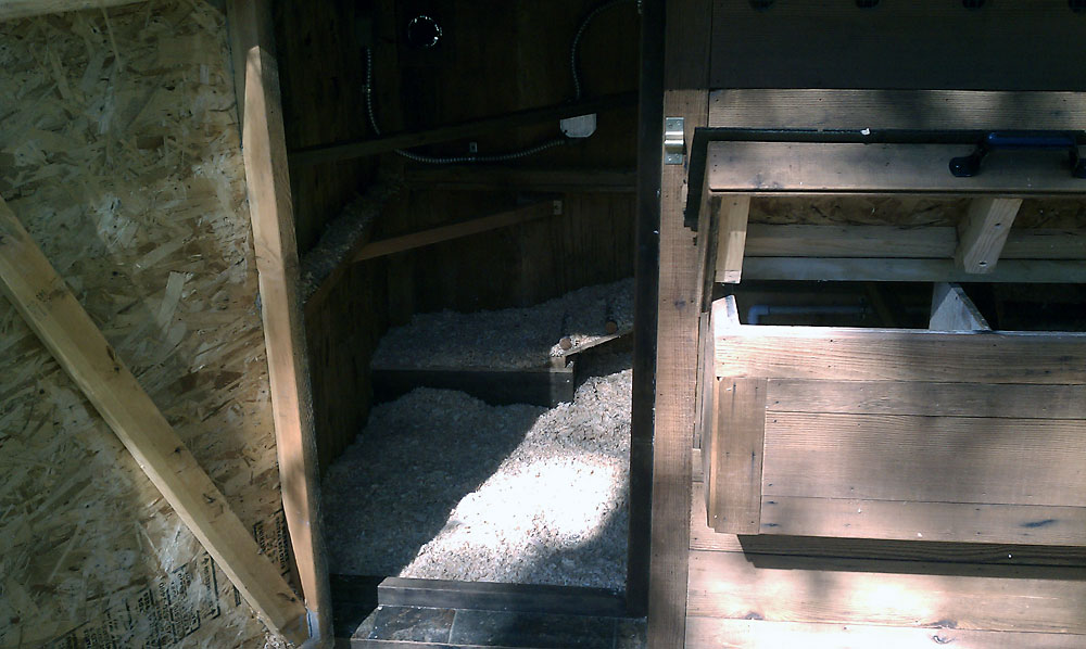
Coop Interior
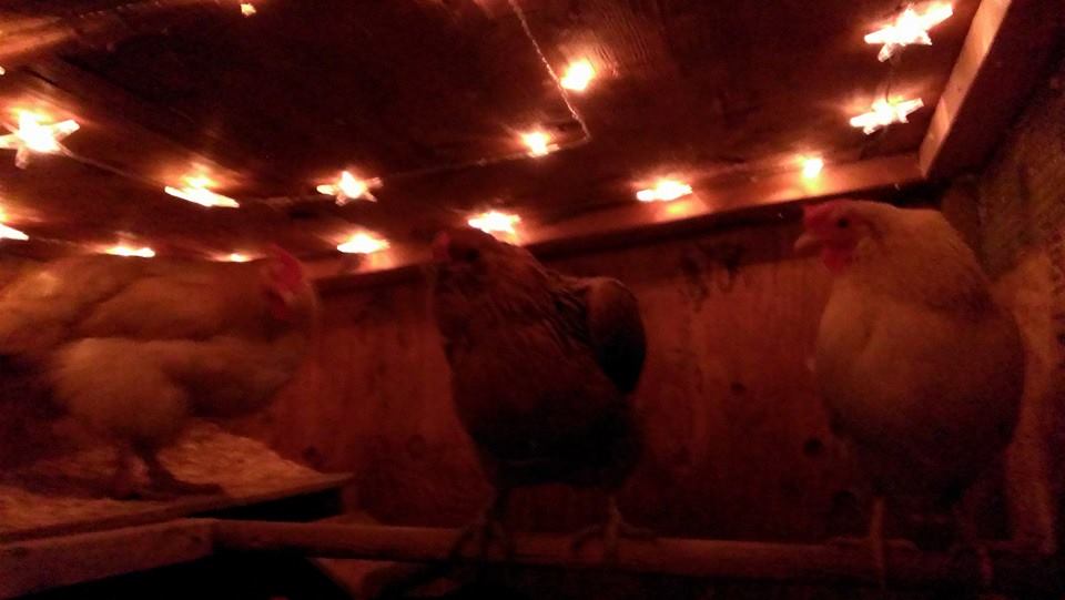
Even though the dimension were already established, given that I used a used dog house, I wanted to give the chickens a few places to hop around and roost. I’ve seen other coops that just have a single roost and maybe that’s fine, but… Click for details >
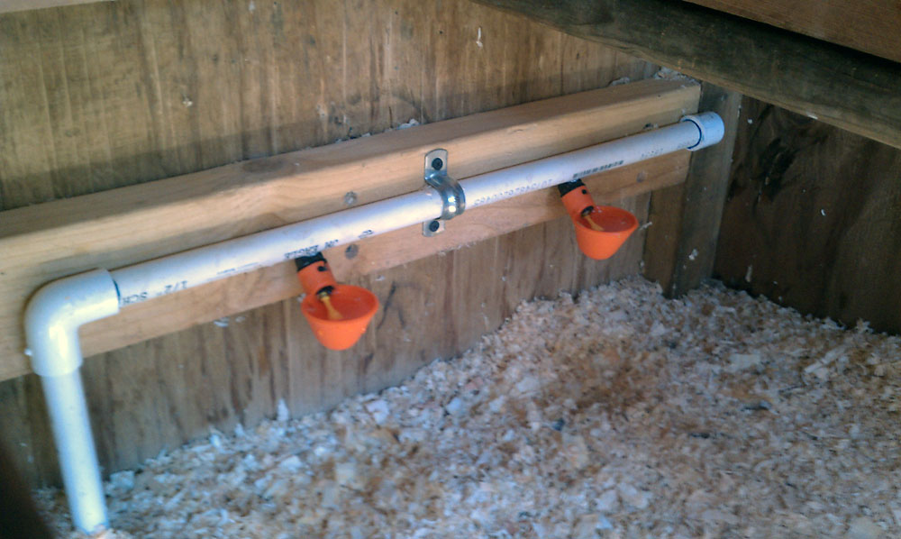
Automatic Chicken Watering System(s)
I thought long and hard about what I wanted to do to keep the babies in fresh water. So after extensive research, I found that the “watering cups” would be the best bet… Click for details >
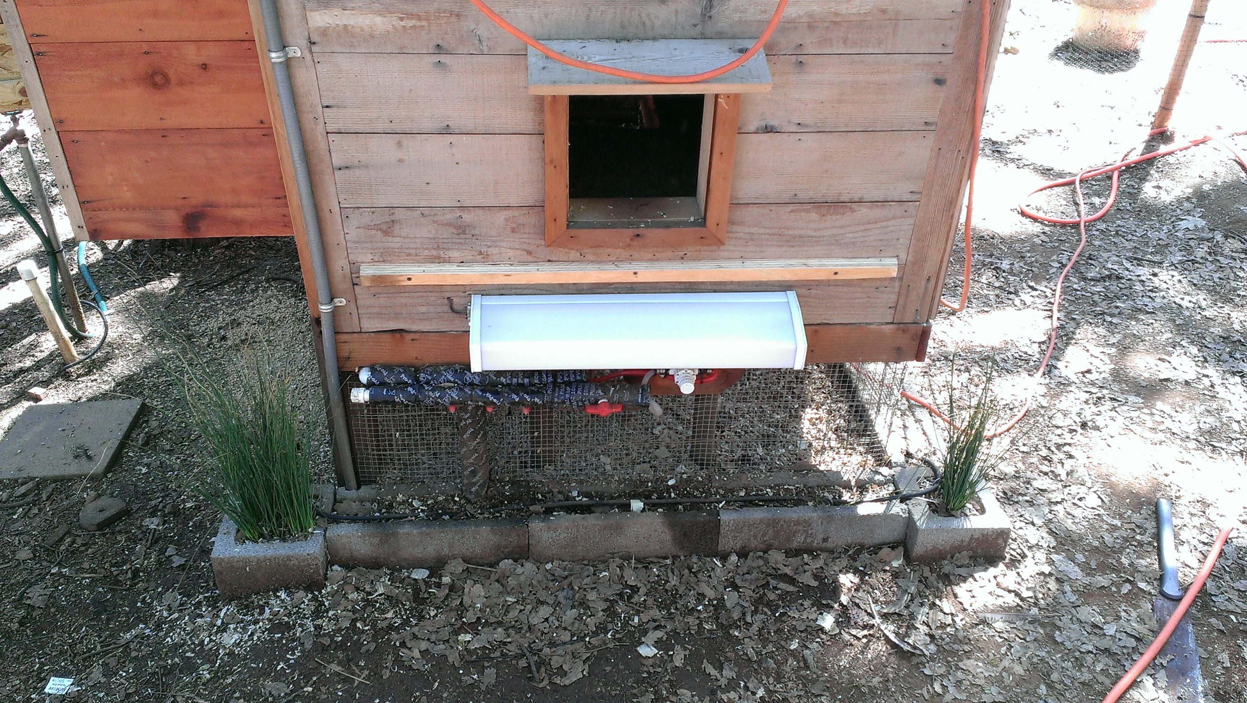
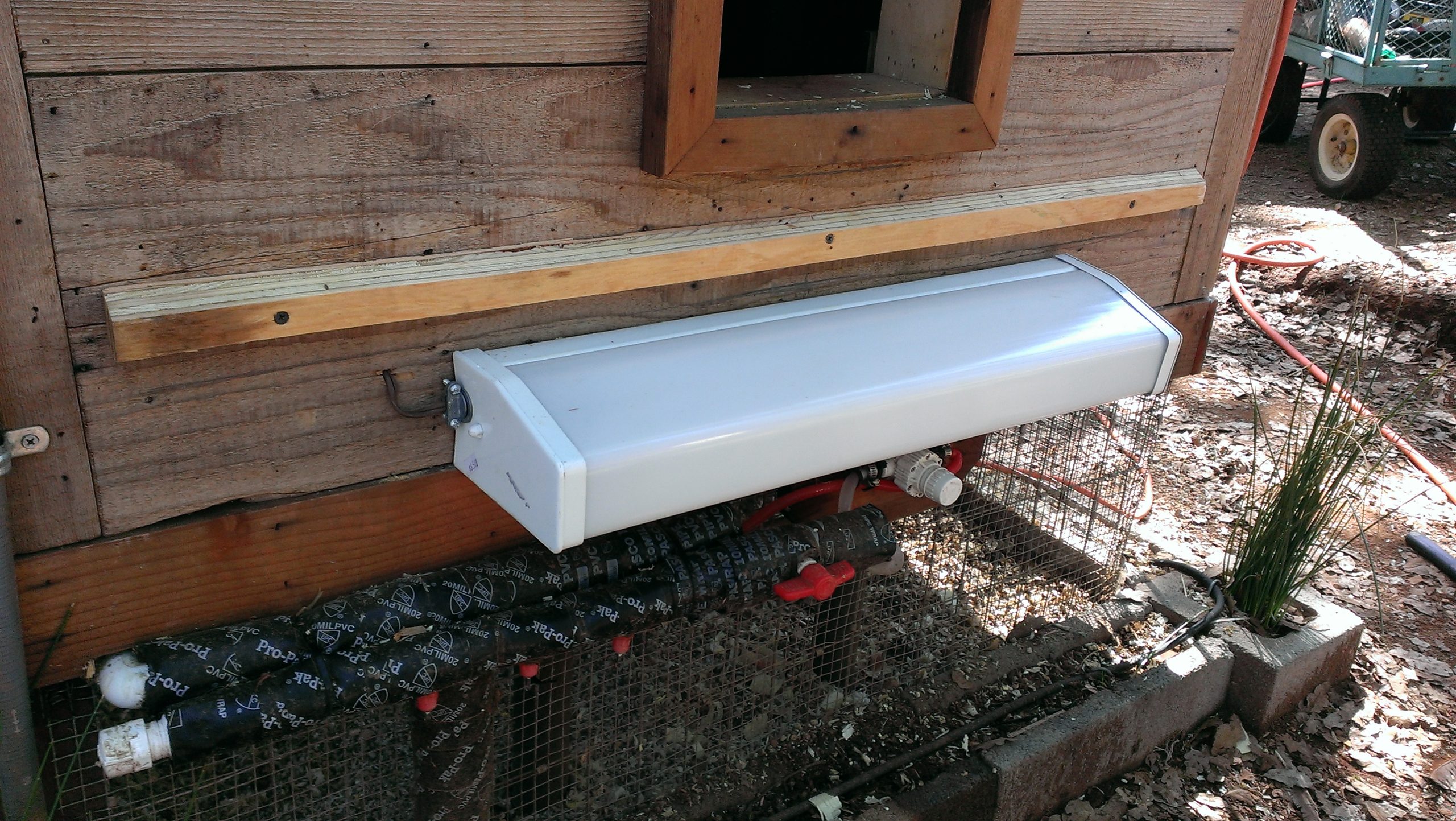
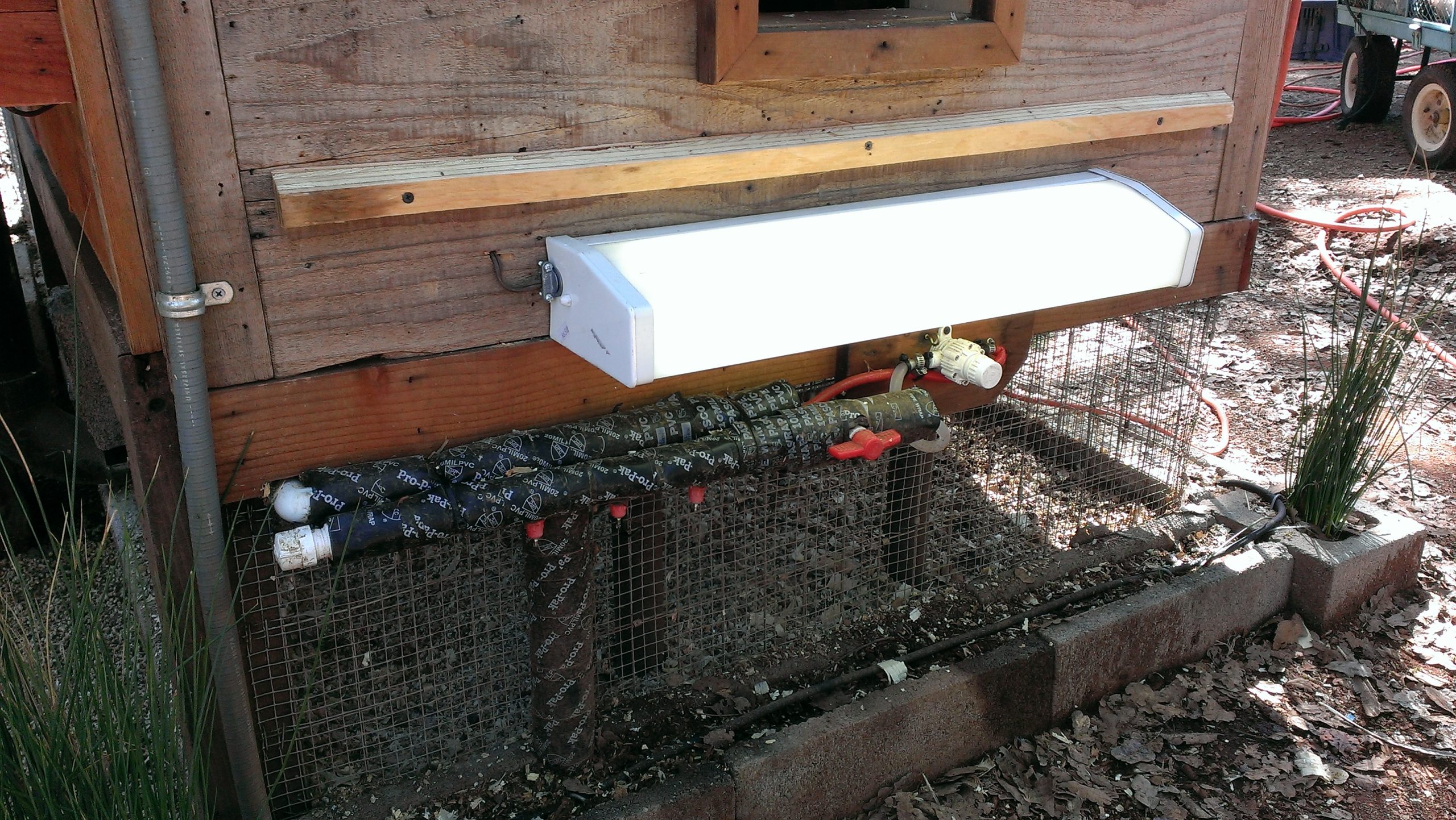
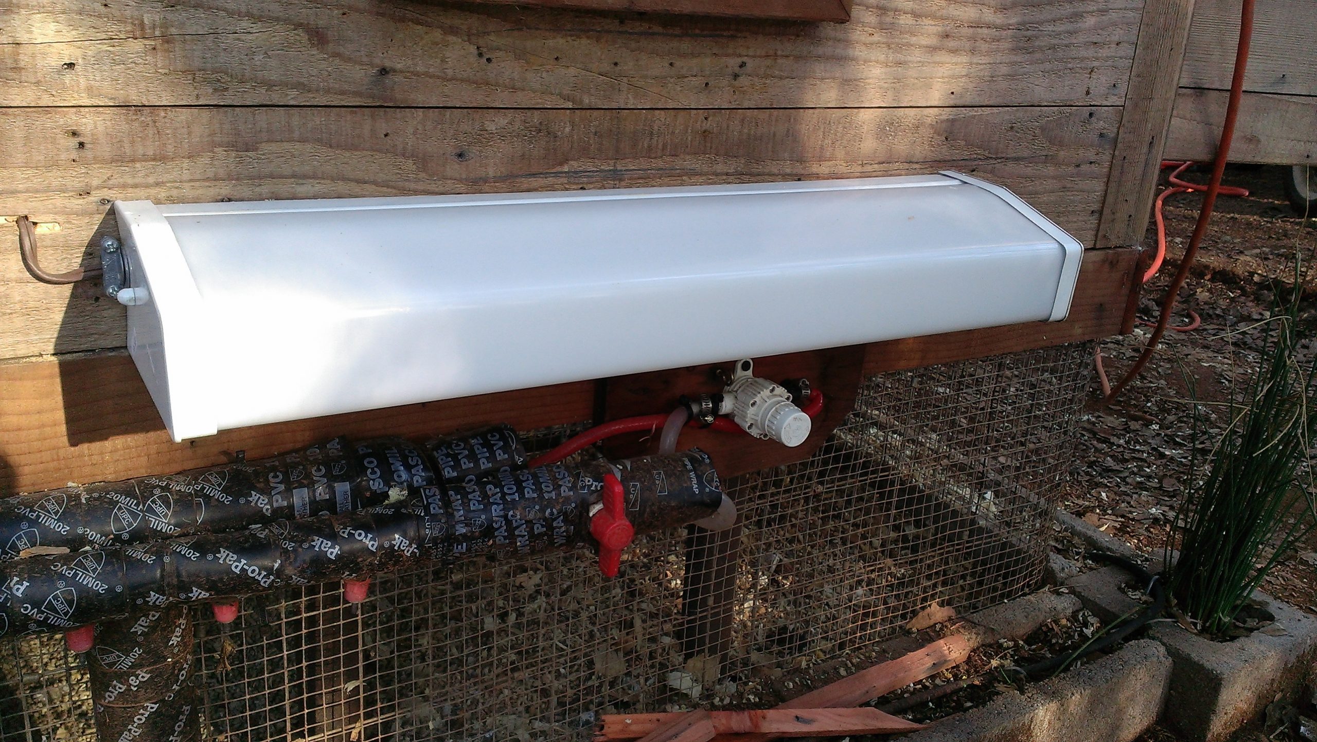
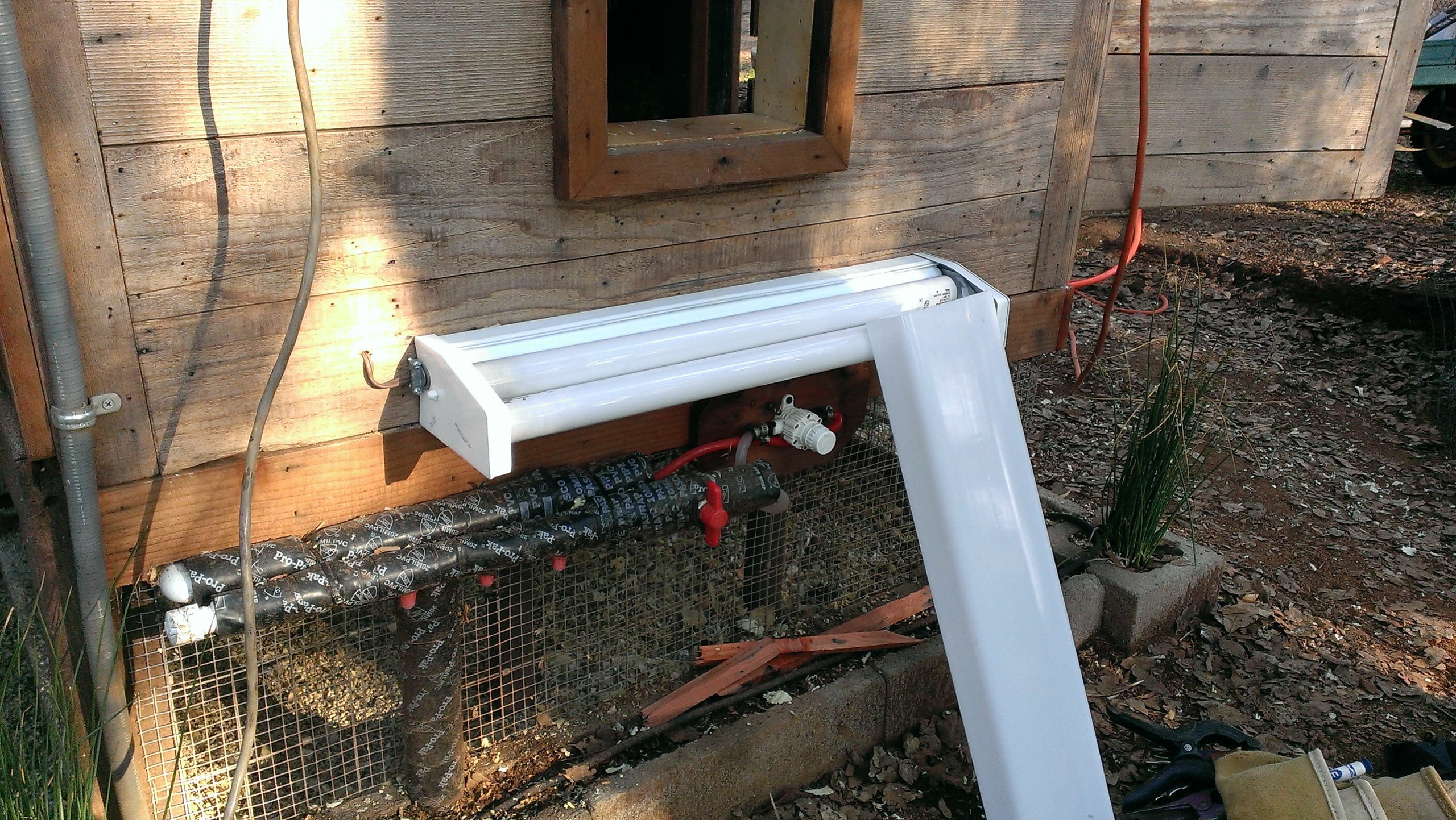
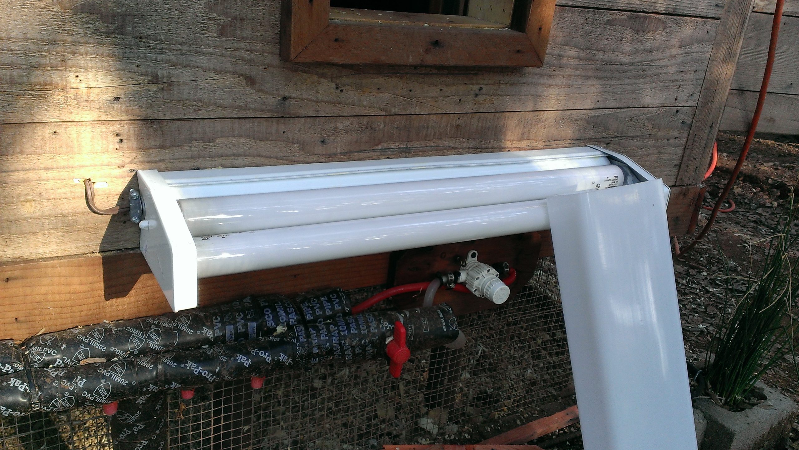
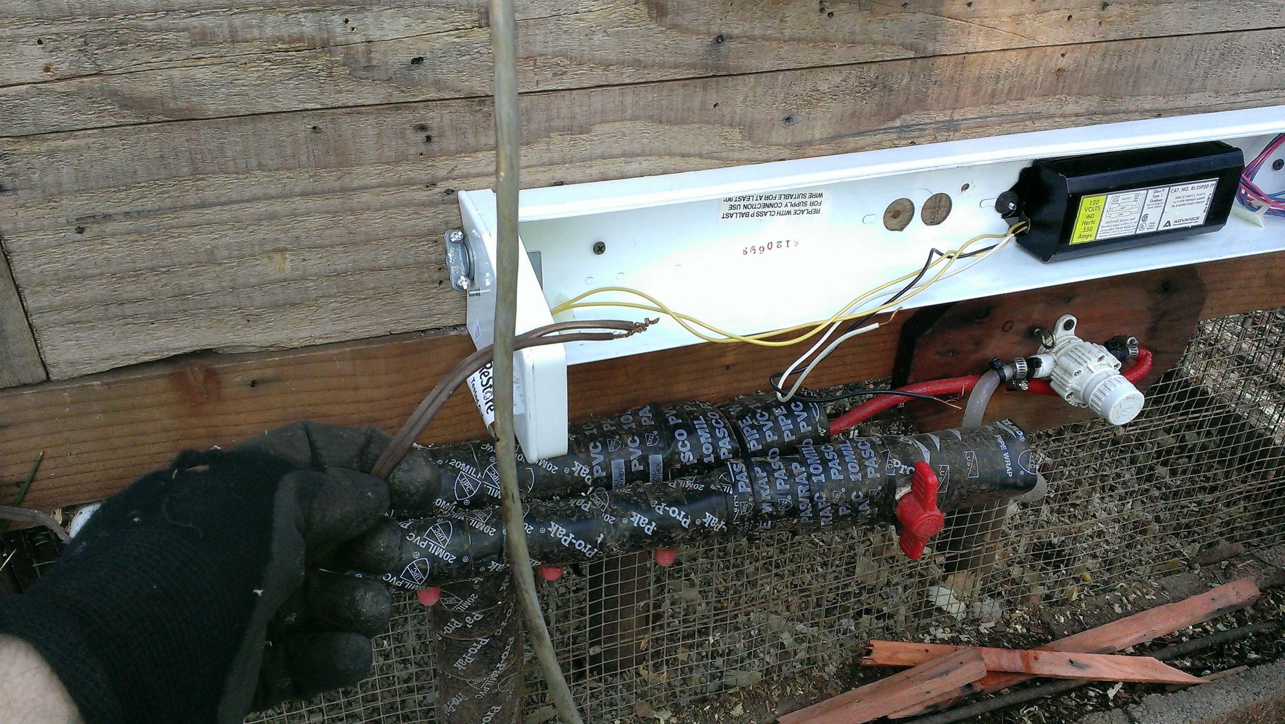
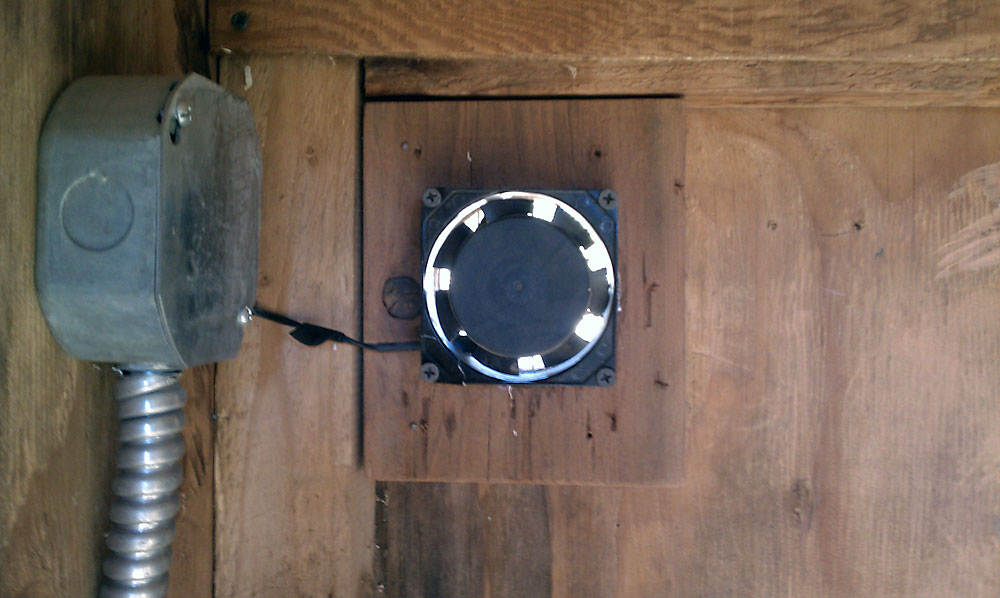
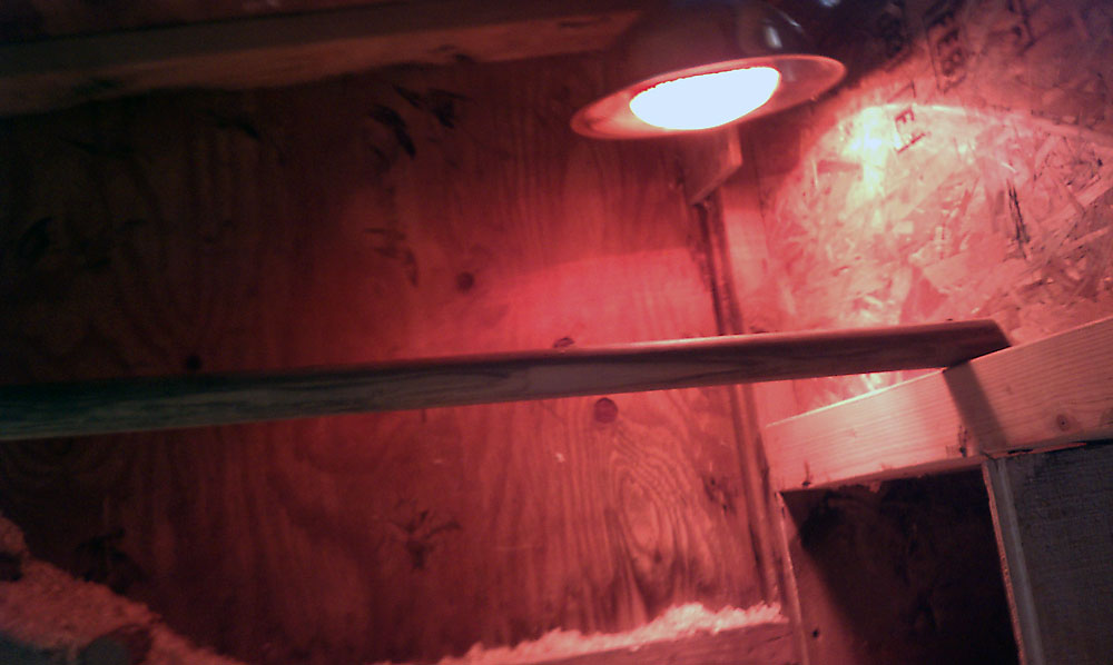
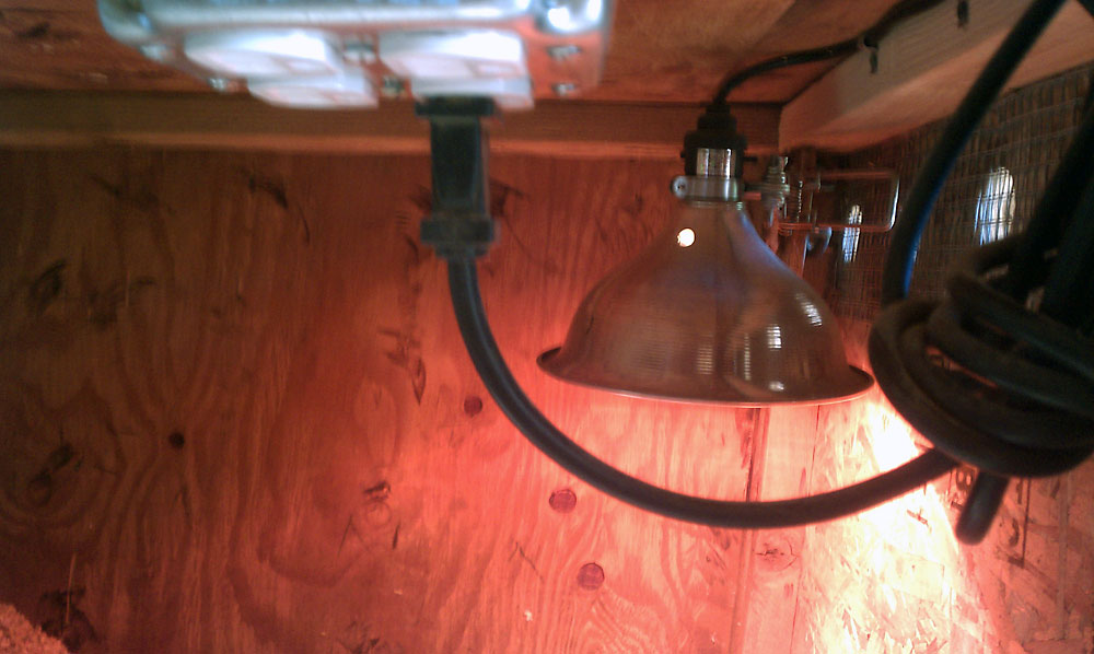
The Chicken Coop Heater(s)
The Automatic Chicken Coop Heater is actually pretty simple:
Essentially 2 lights (1 halogen and 1 florescent bulb) triggered on an off by temperatures.
There are 2 different systems:Click for details >
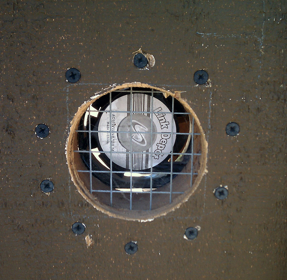
The Chicken Coop Cooling System
details coming soon…
Chicken Web Cam

Live Chicken Cam in Auburn CA
I wanted to be able to check on the girls in the coop, especially when we’re away. Having a web-enabled camera allowed just for that (ok, and maybe I went a bit overboard with the servo-driven sweeping pattern of the camera… but hey, I couldn’t see them all with such a tight shot. Click for details >
Predator Motion Detector Alarm & Deterrent for Chickens
The Coop Run
details coming soon…
The Exterior Run
details coming soon…
(Semi) Automatic Chicken Feeder
Based on what others I had seen, I created this from 3″ ABS pipe. I already had most of the materials, except the cap and threaded plug, which I bought for under $5 at the Habitat for Humanity Restore… Click for details >

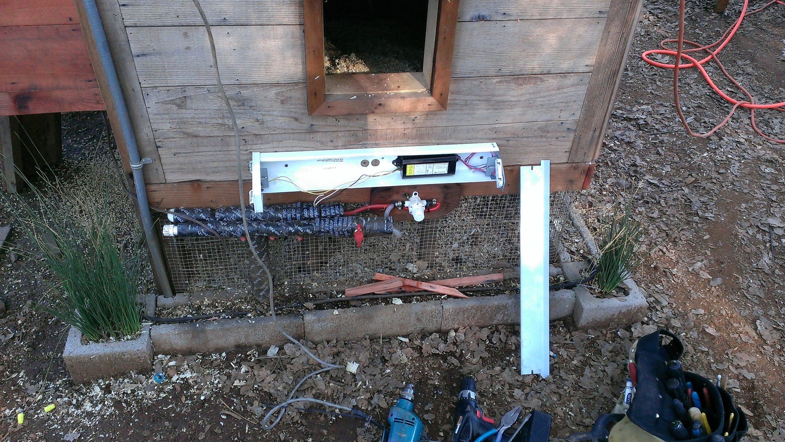
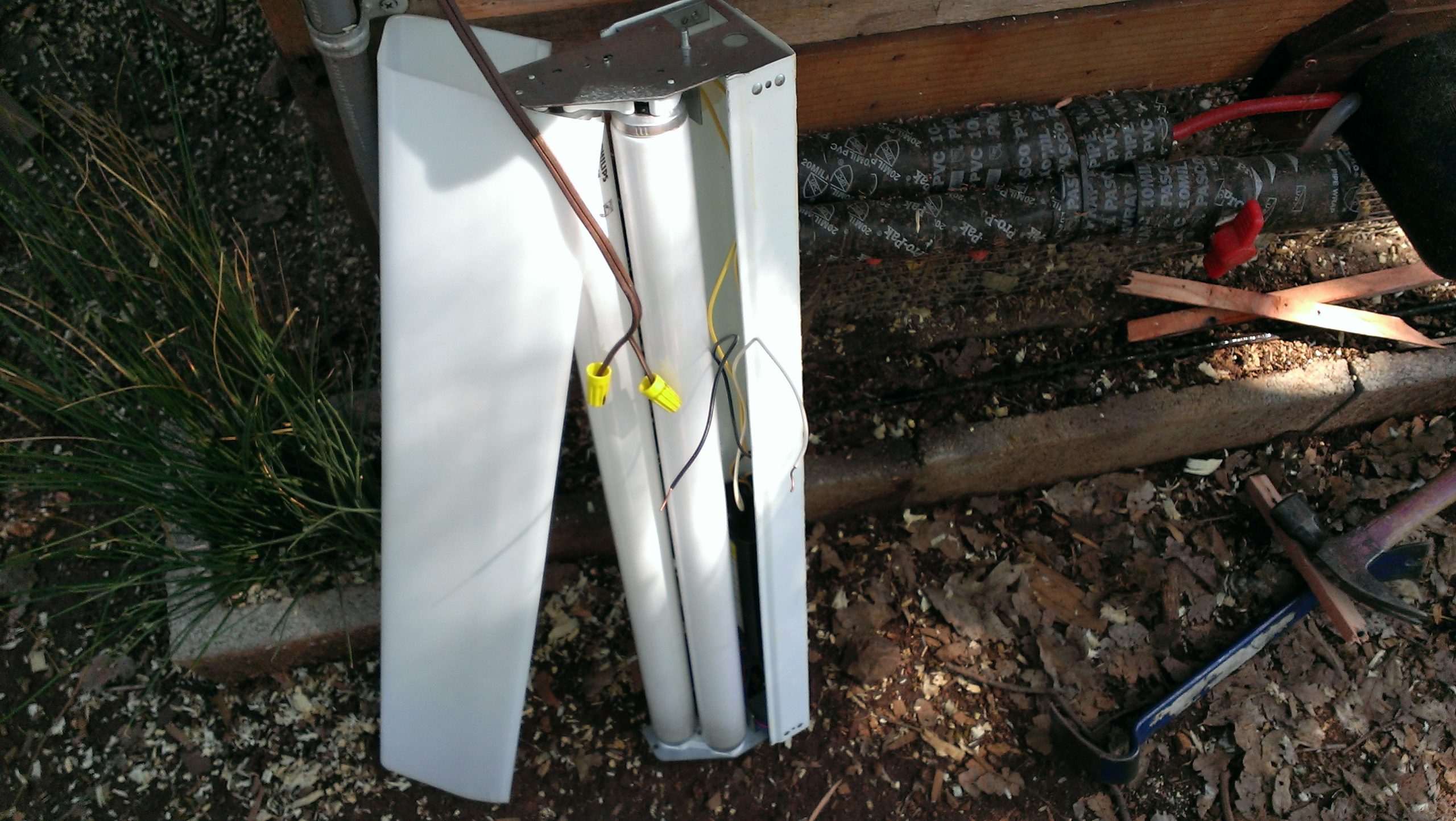
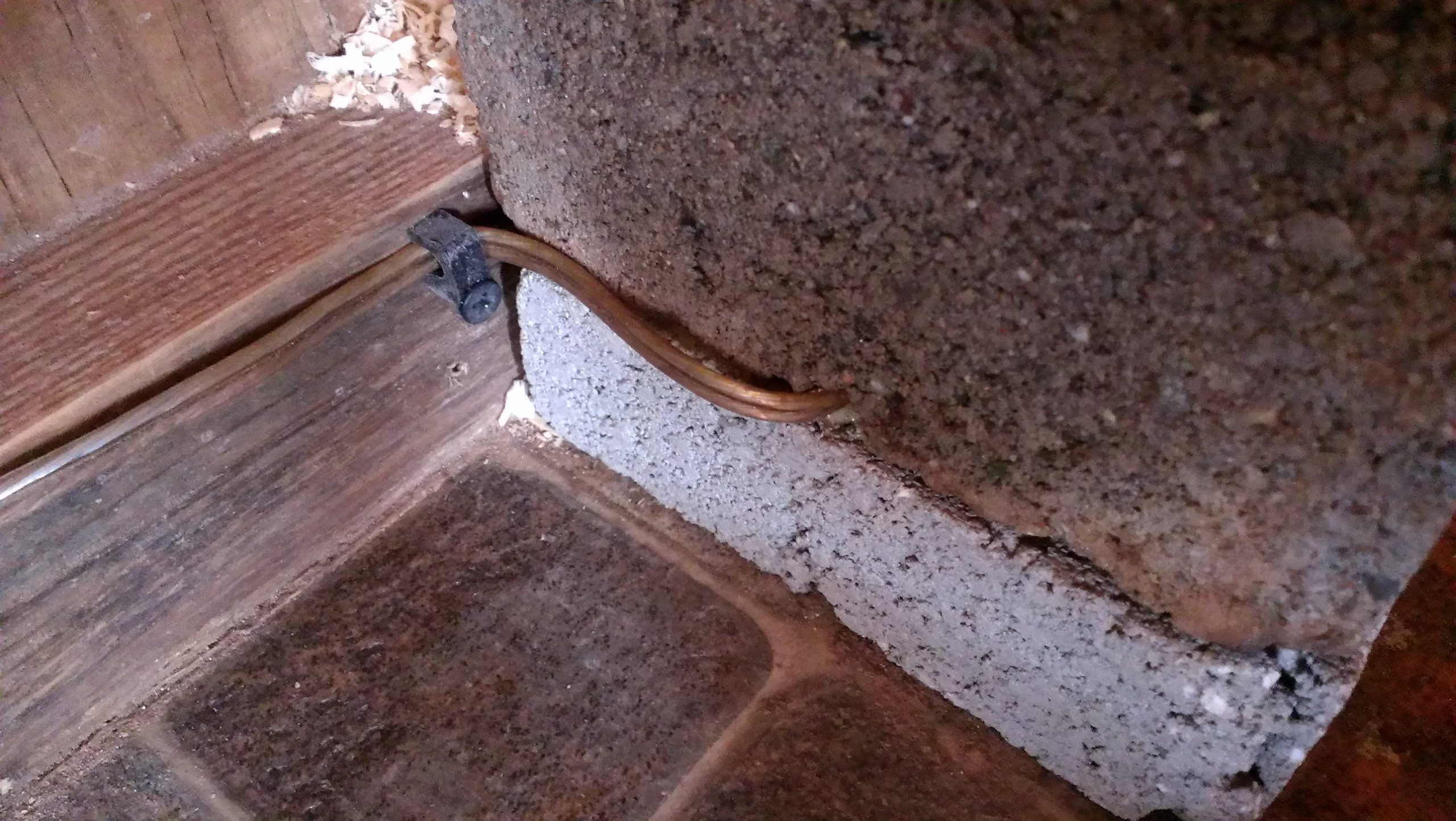
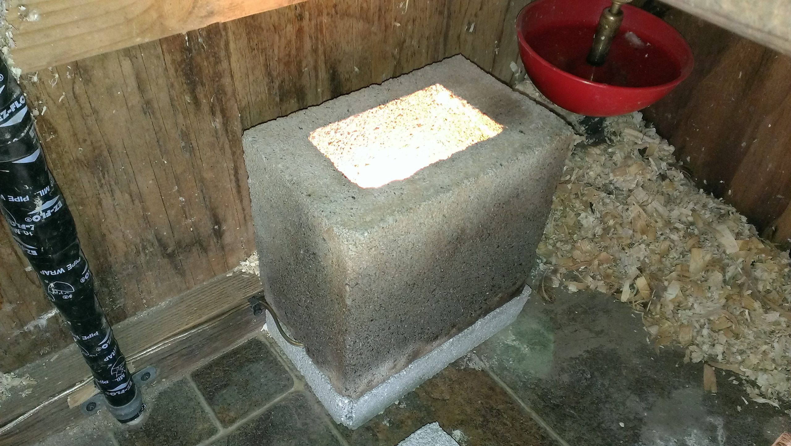

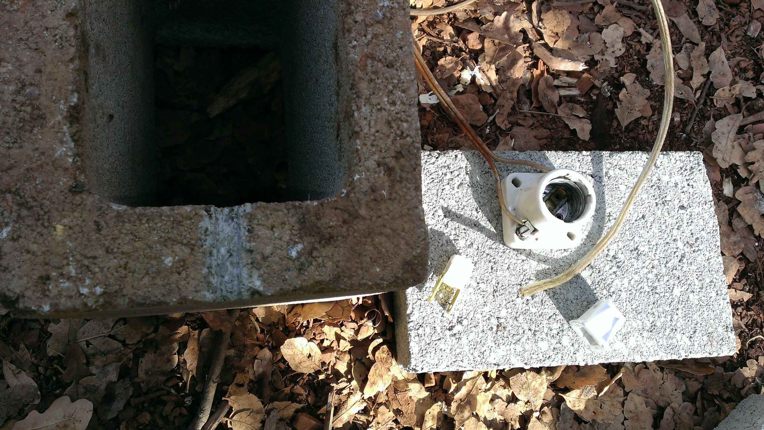
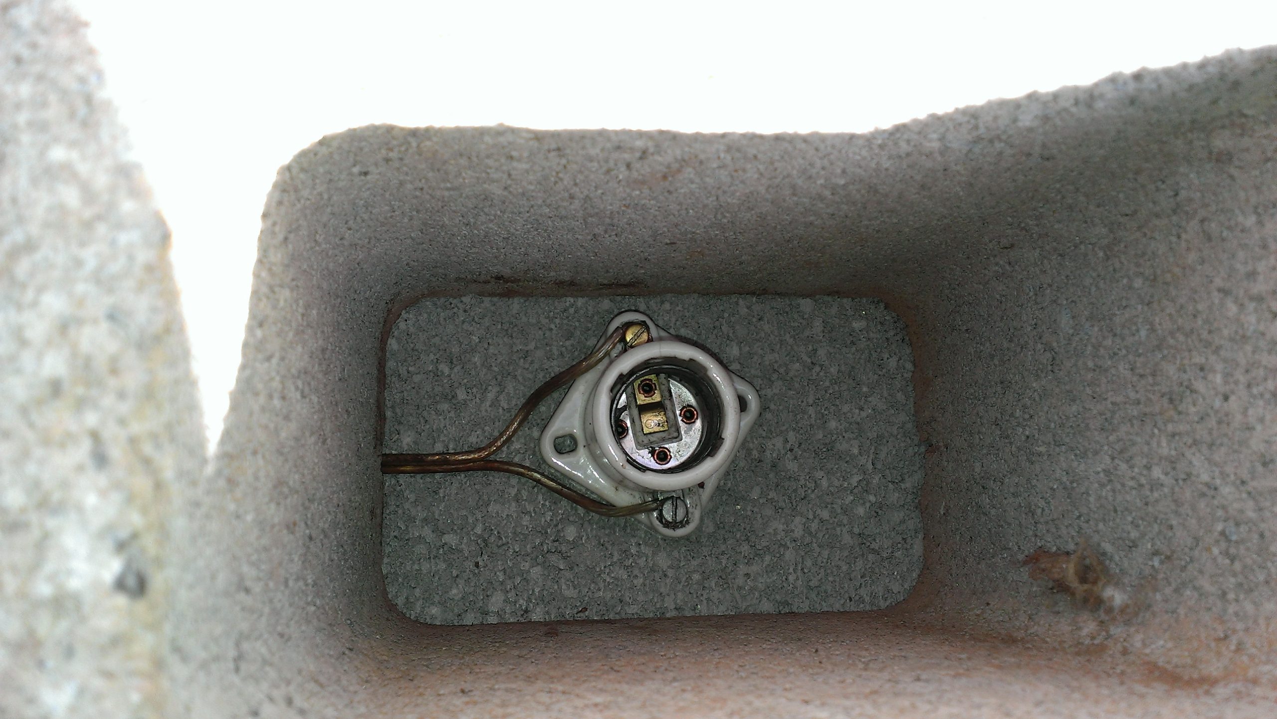
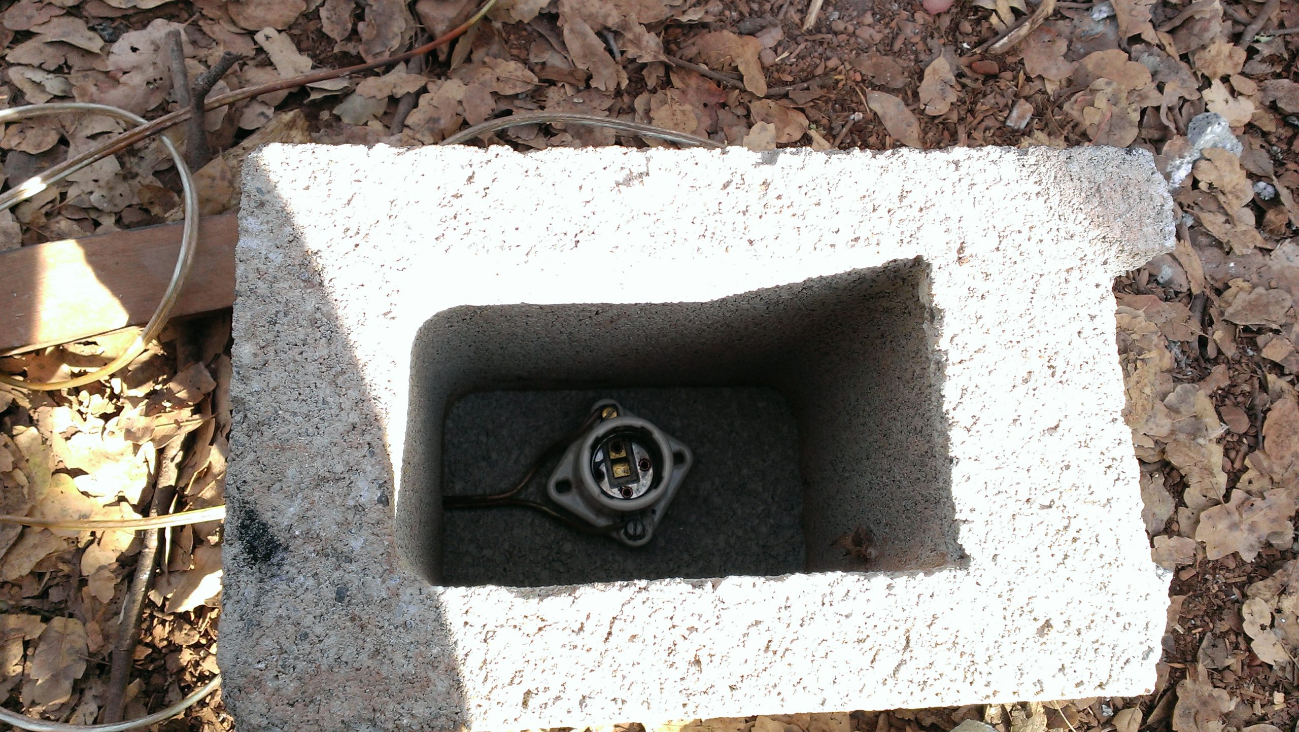
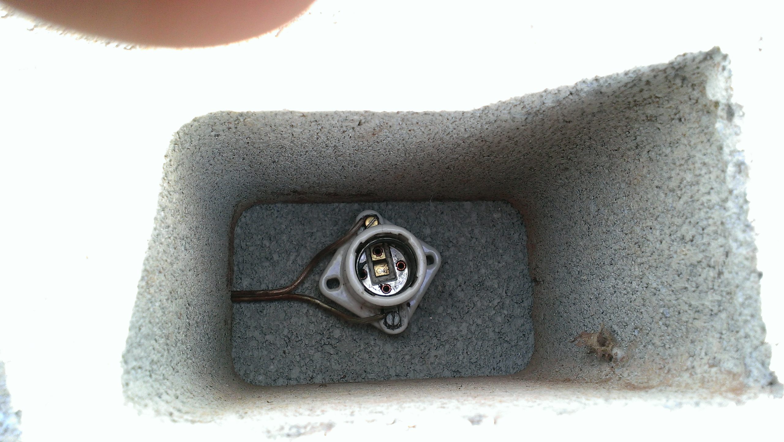
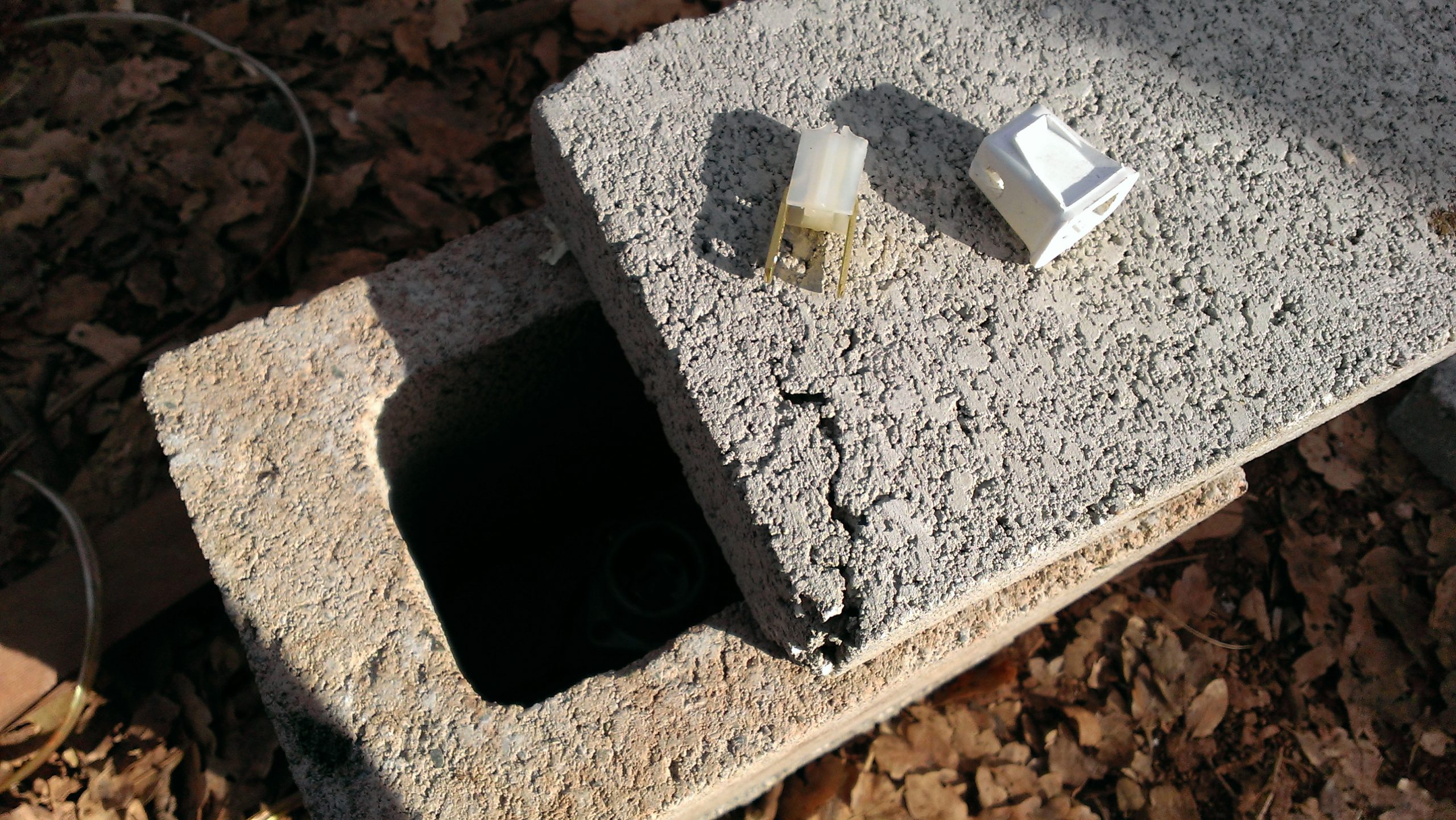



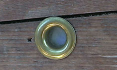
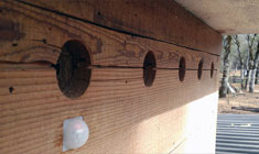
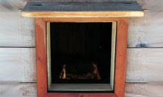
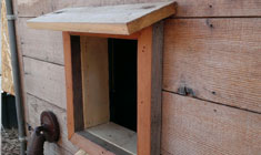
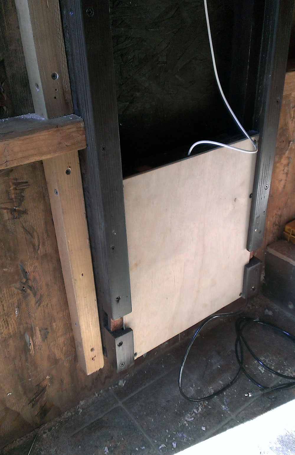
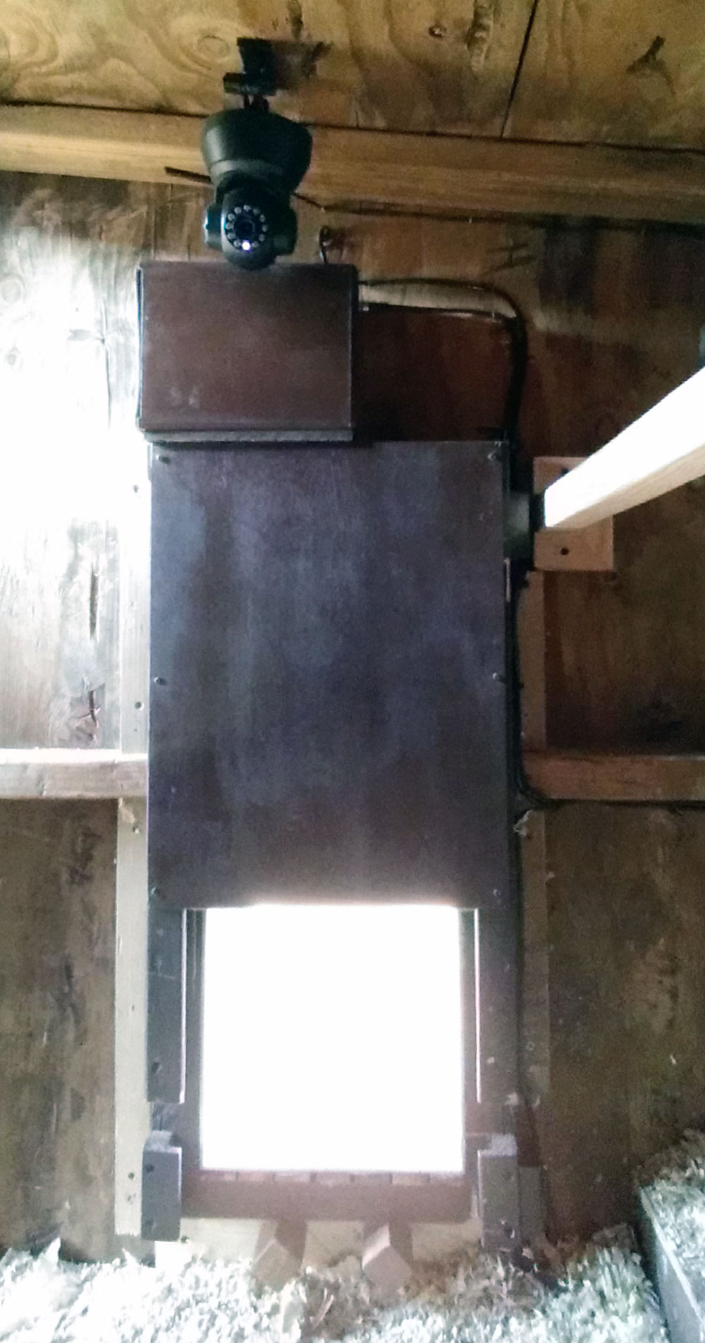
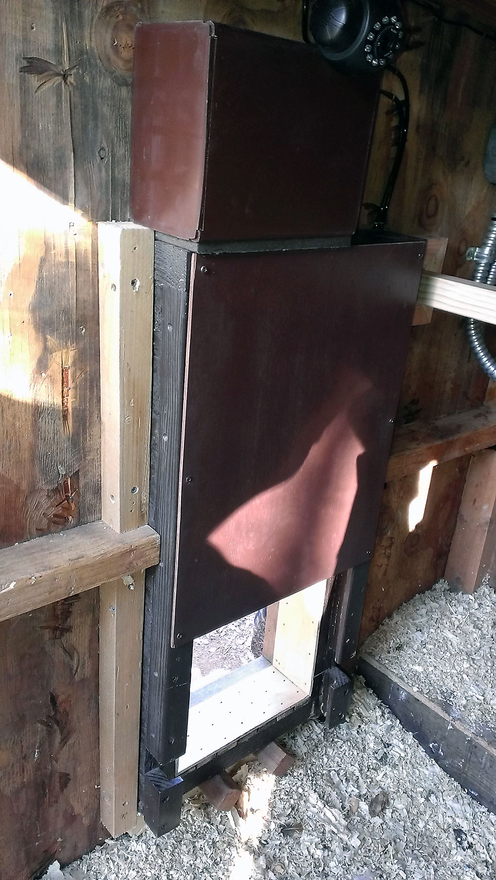
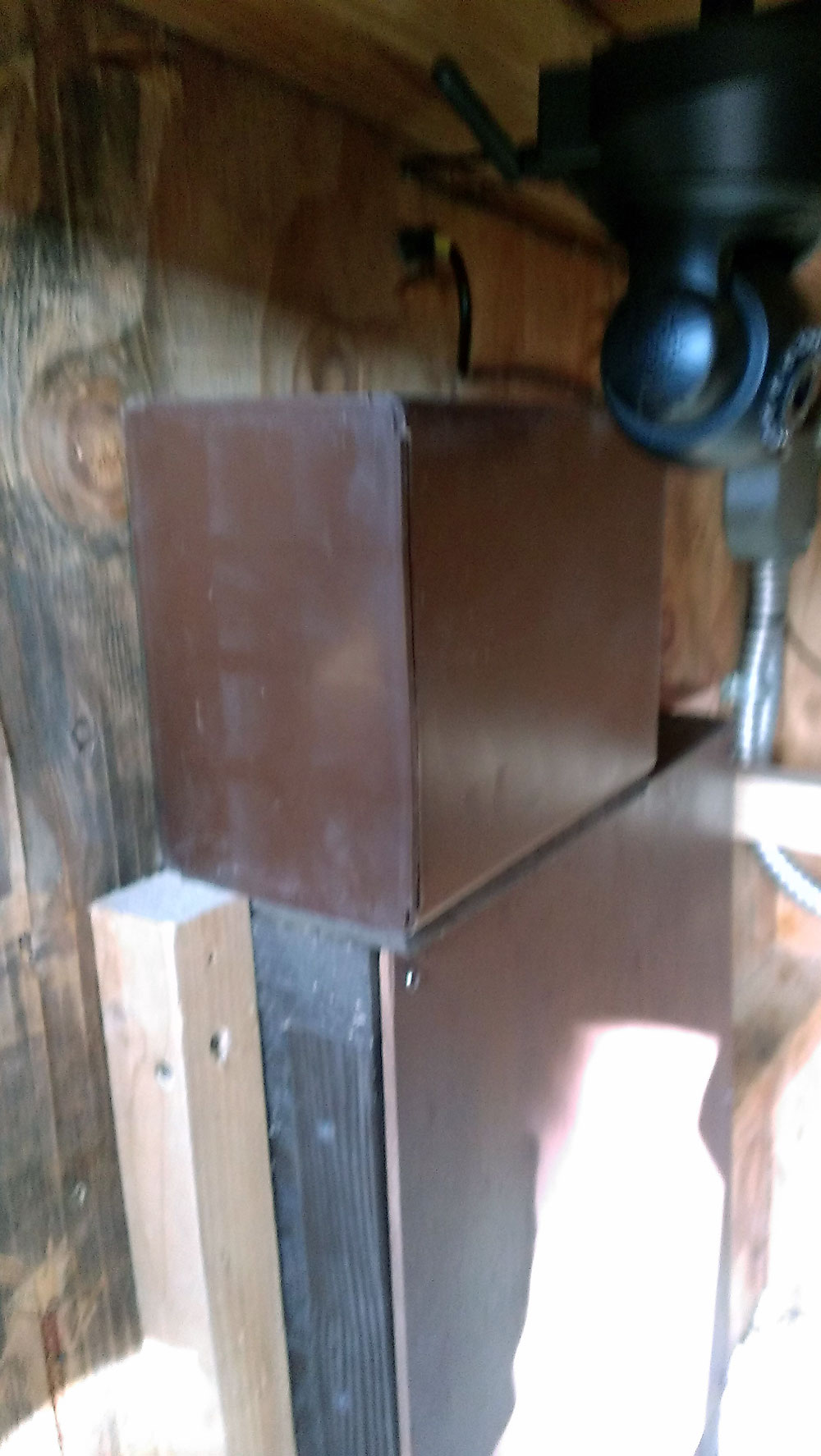
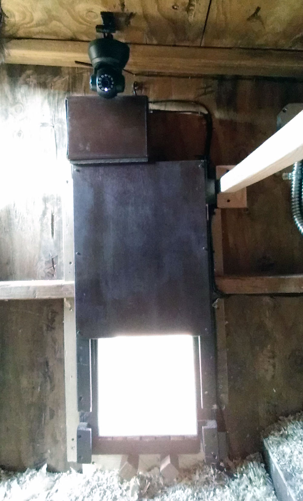
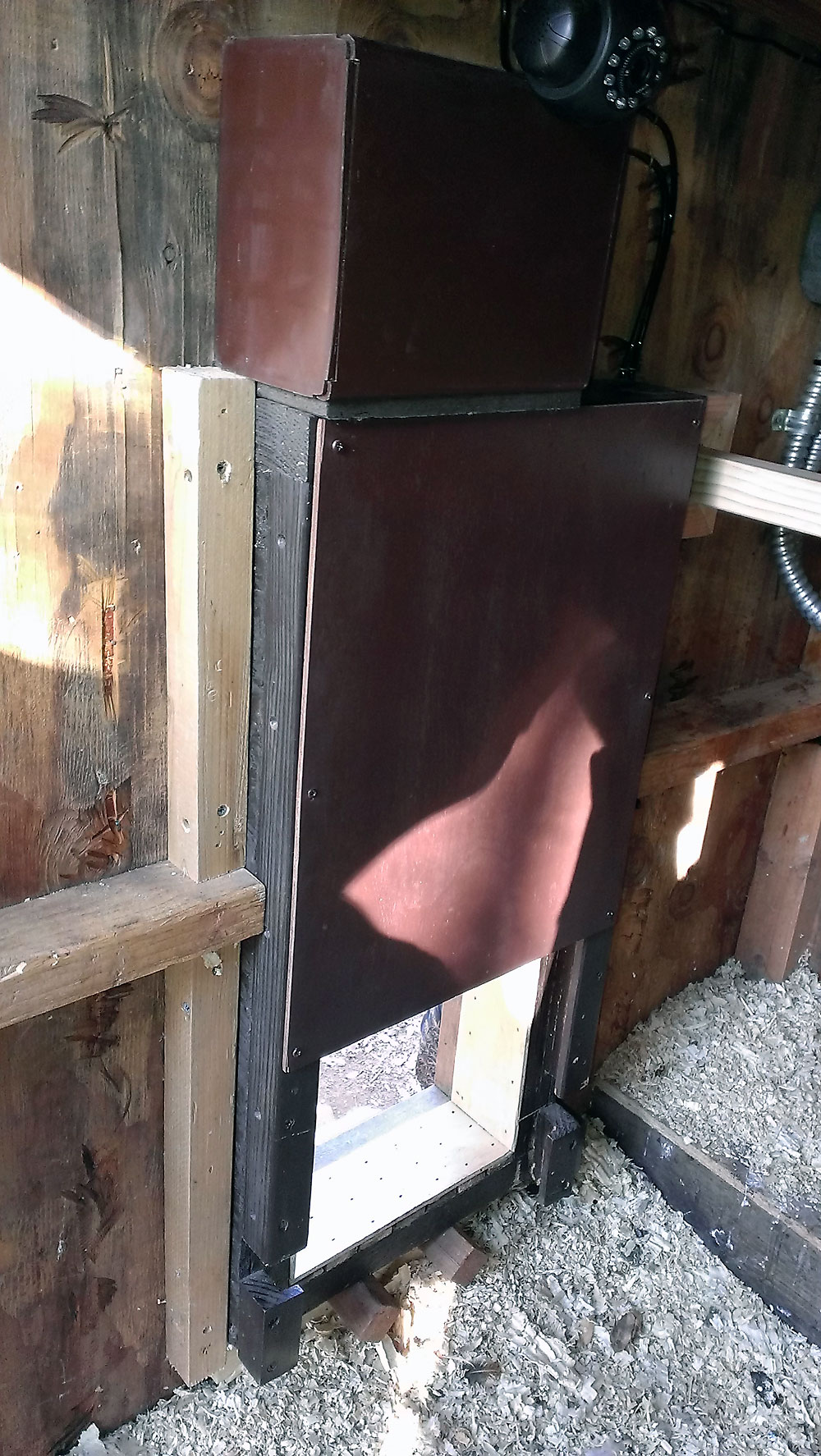
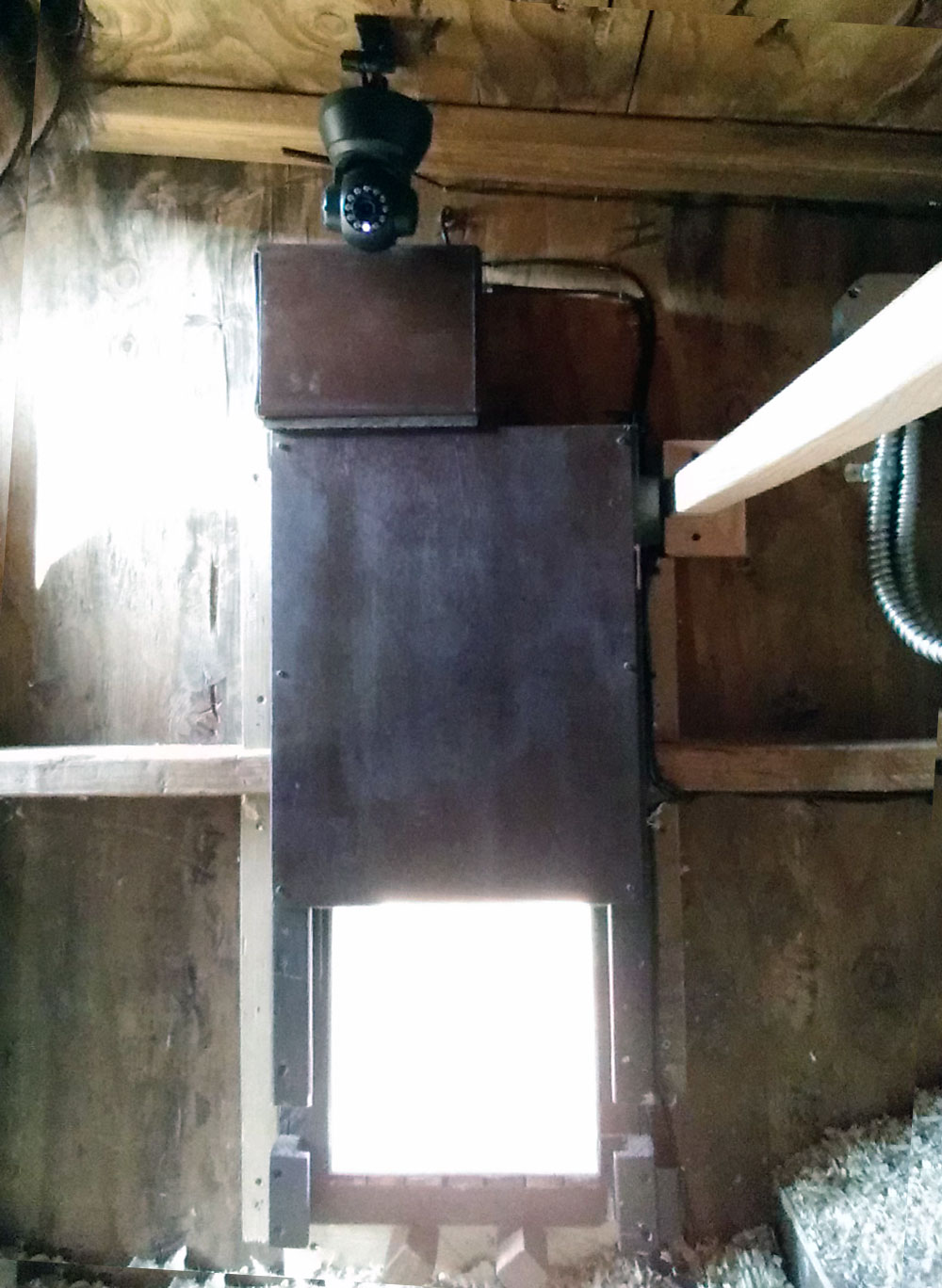
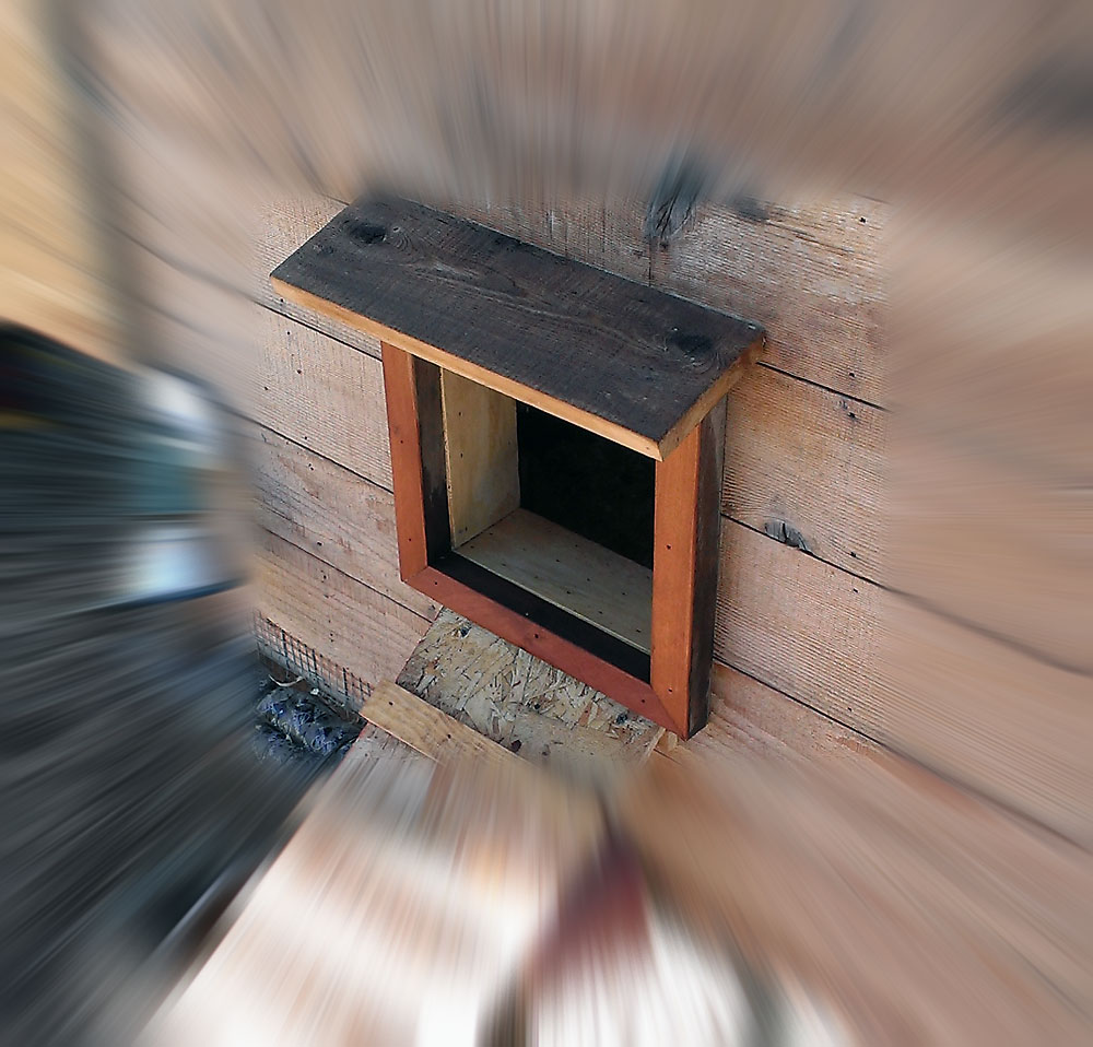
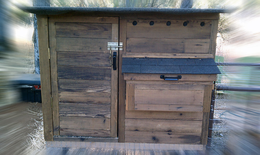
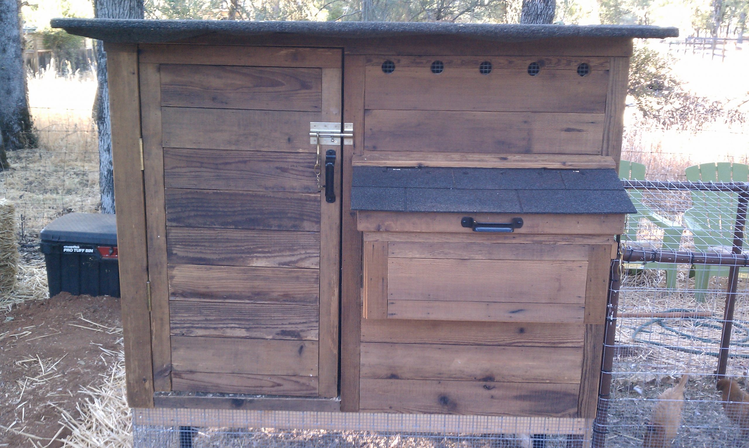
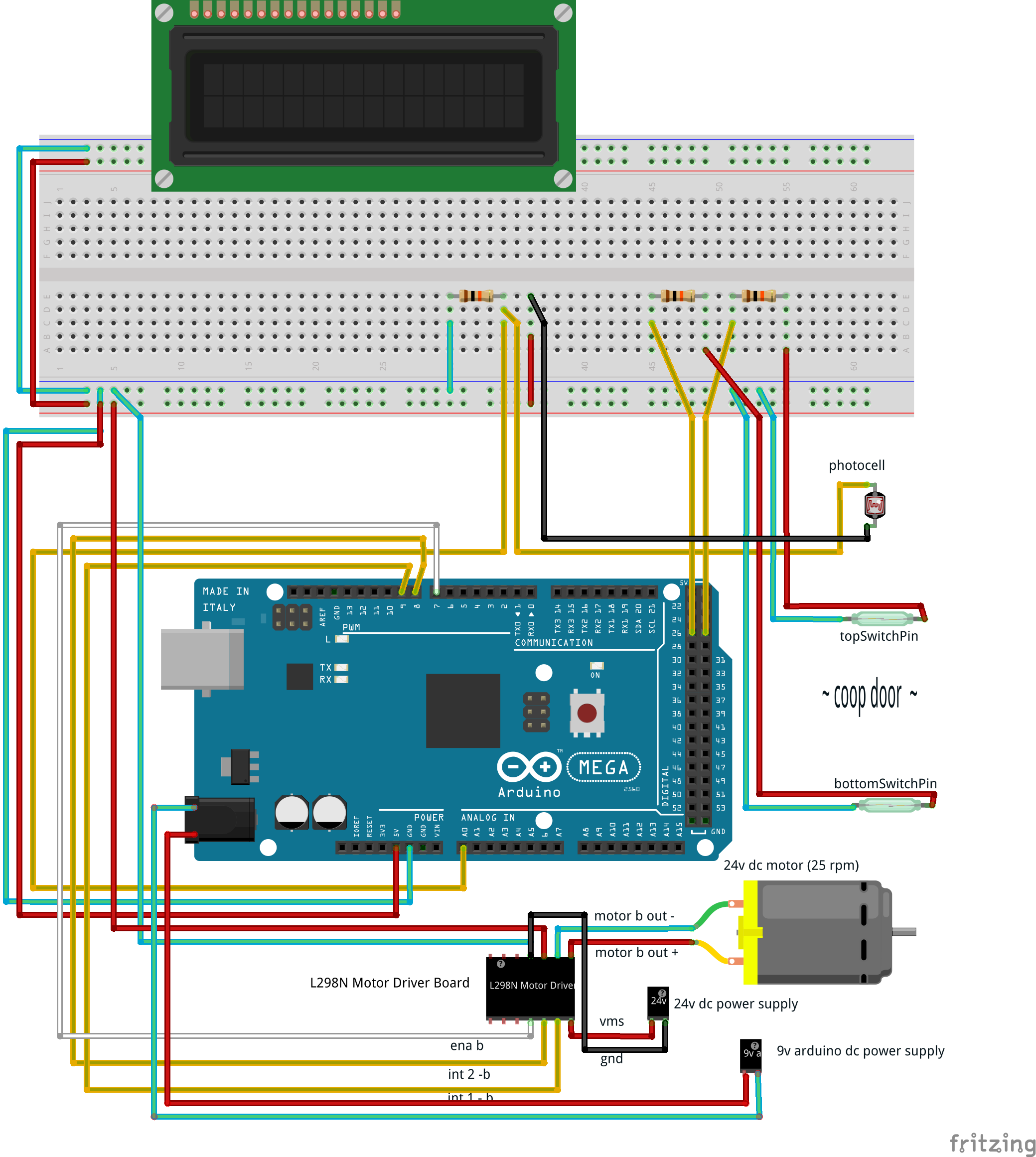
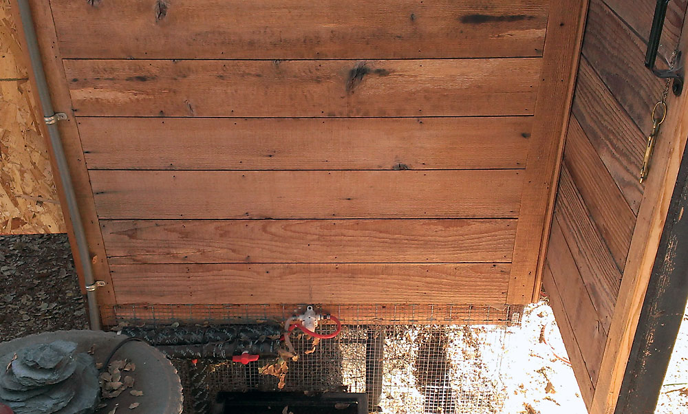
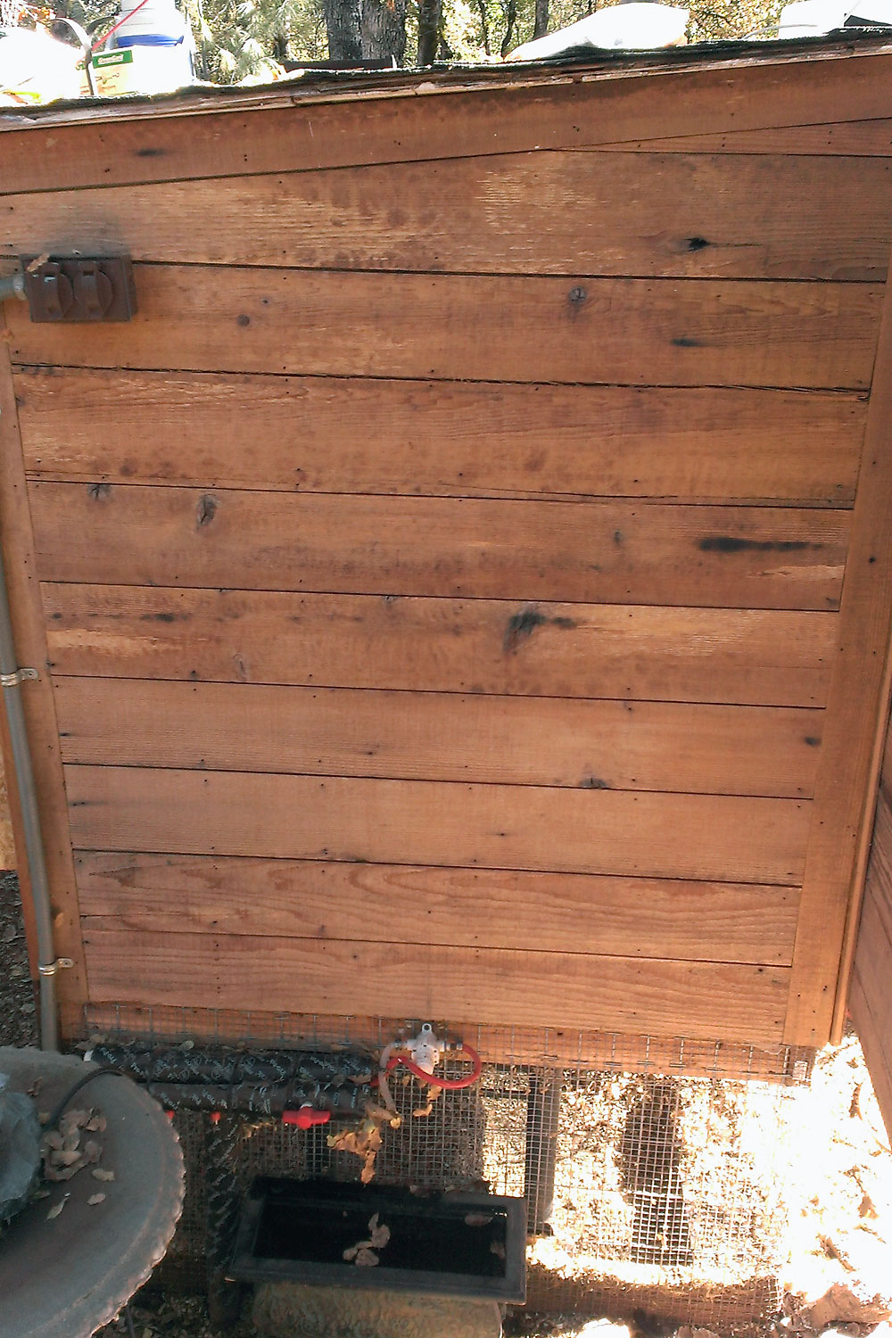
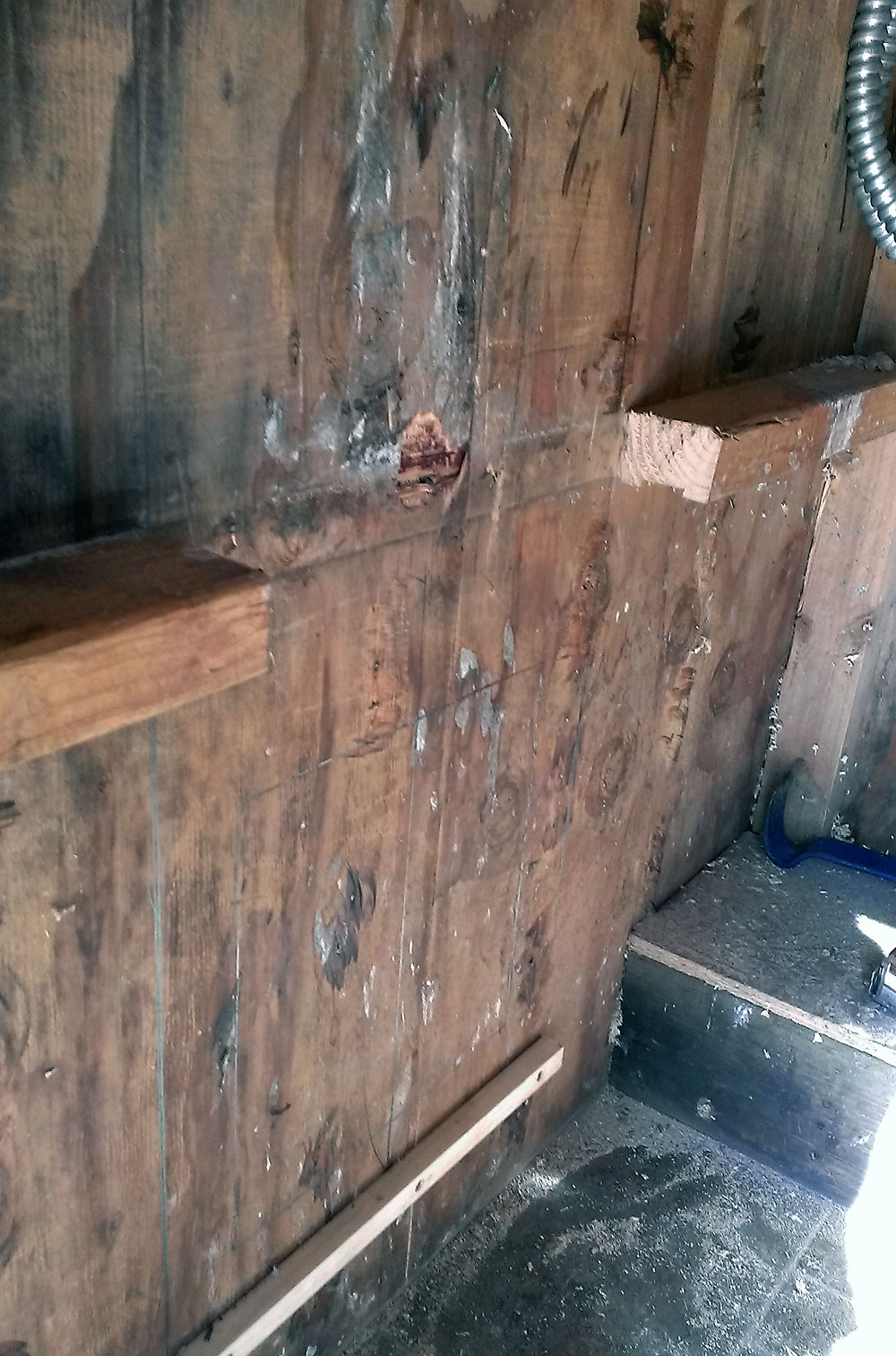

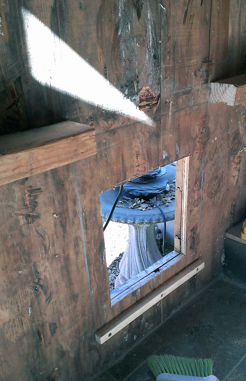
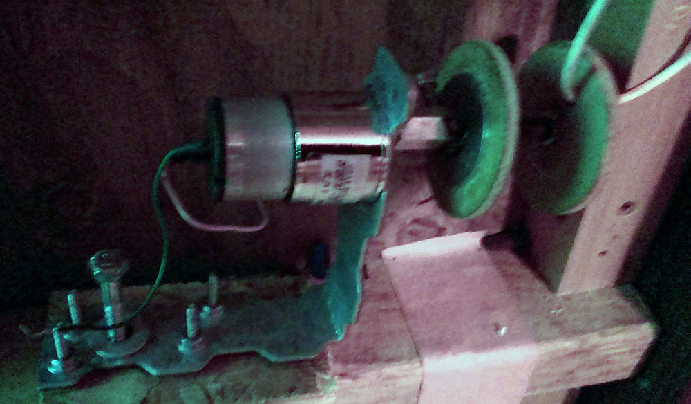
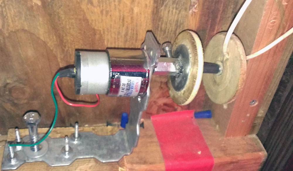

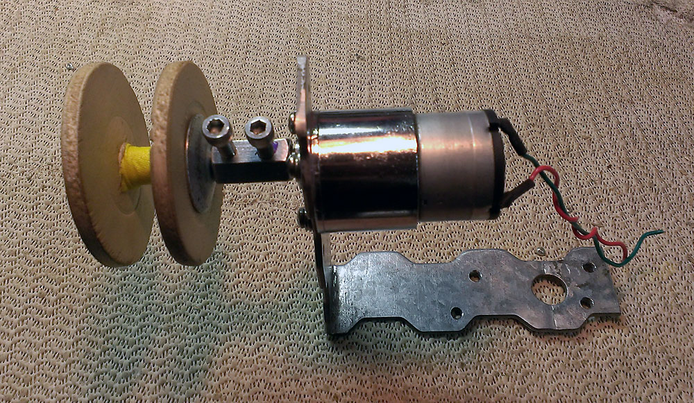
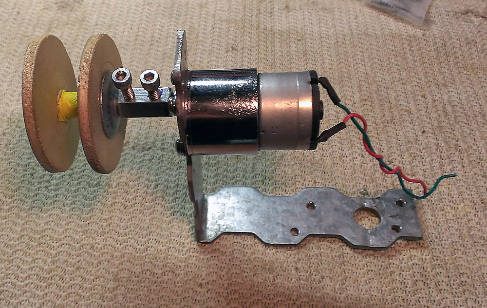
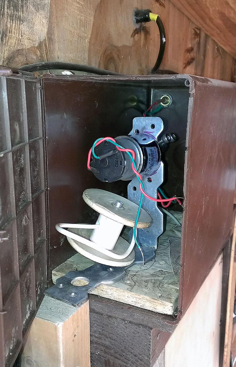
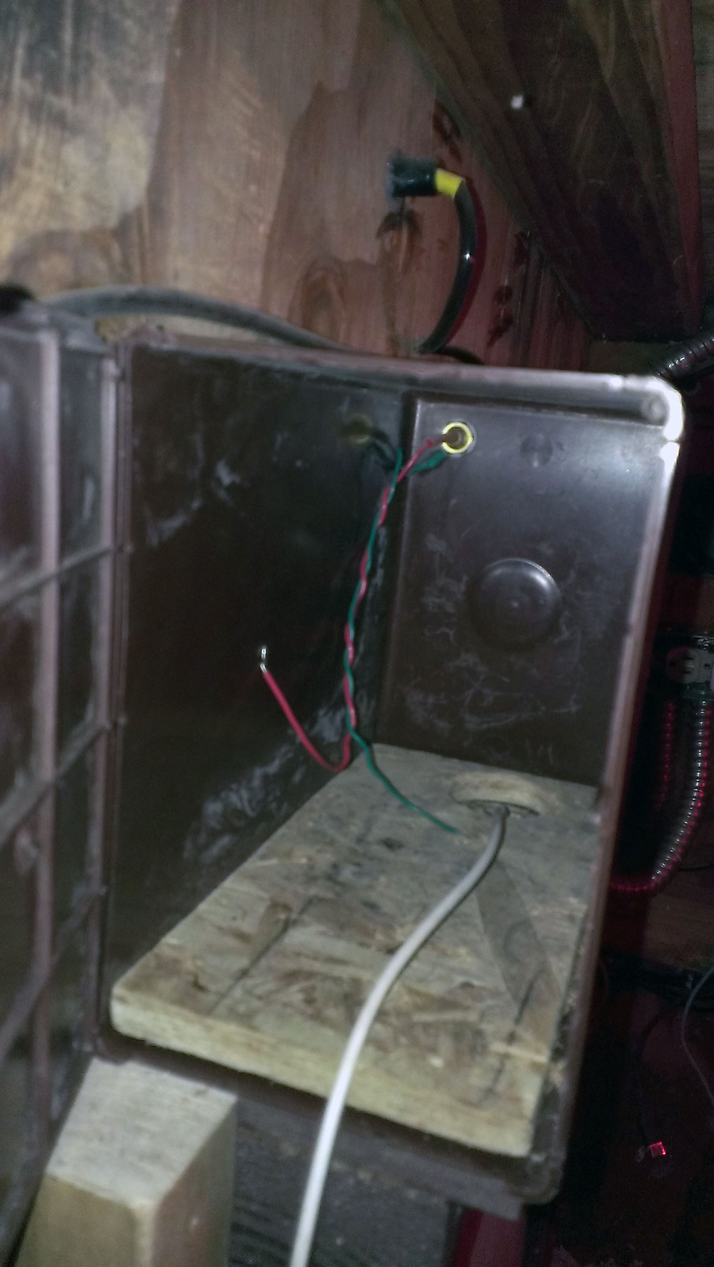
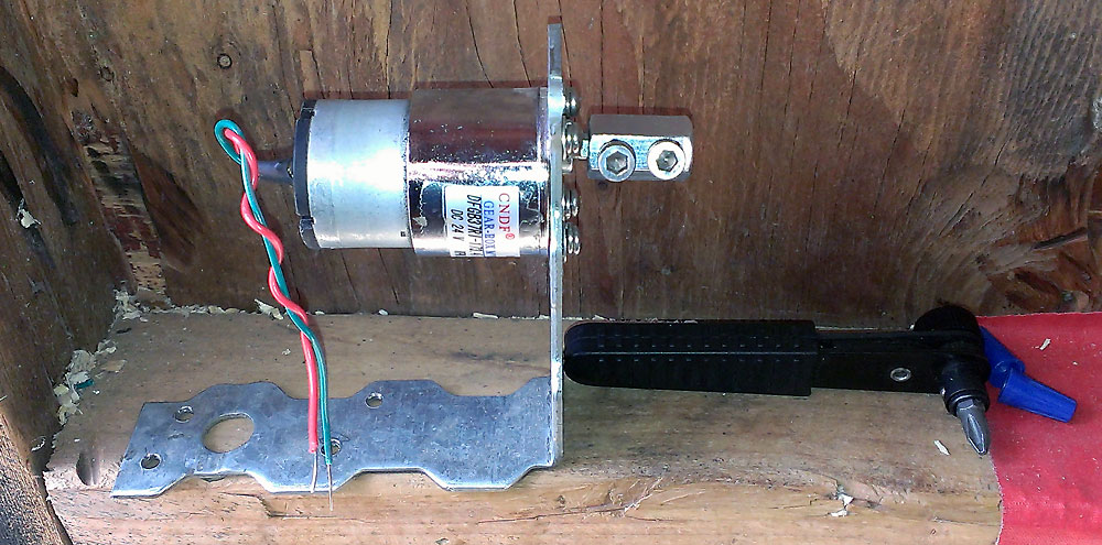
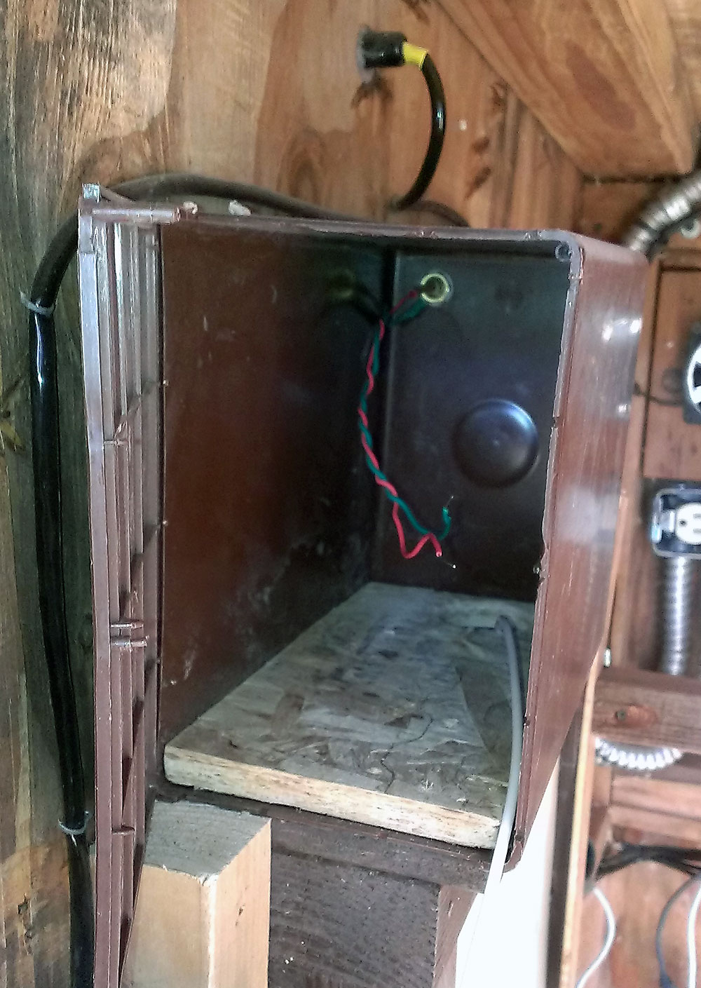
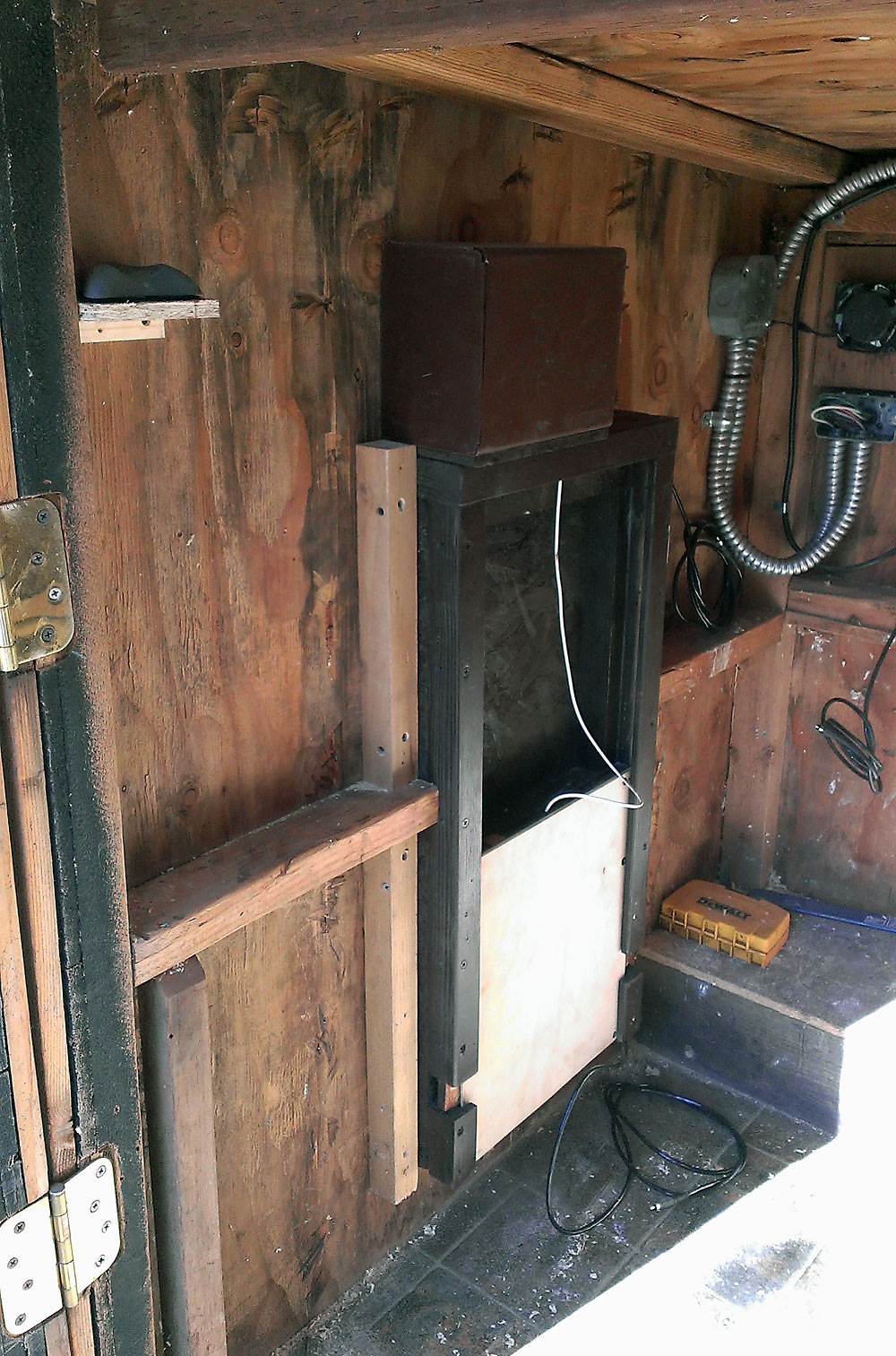
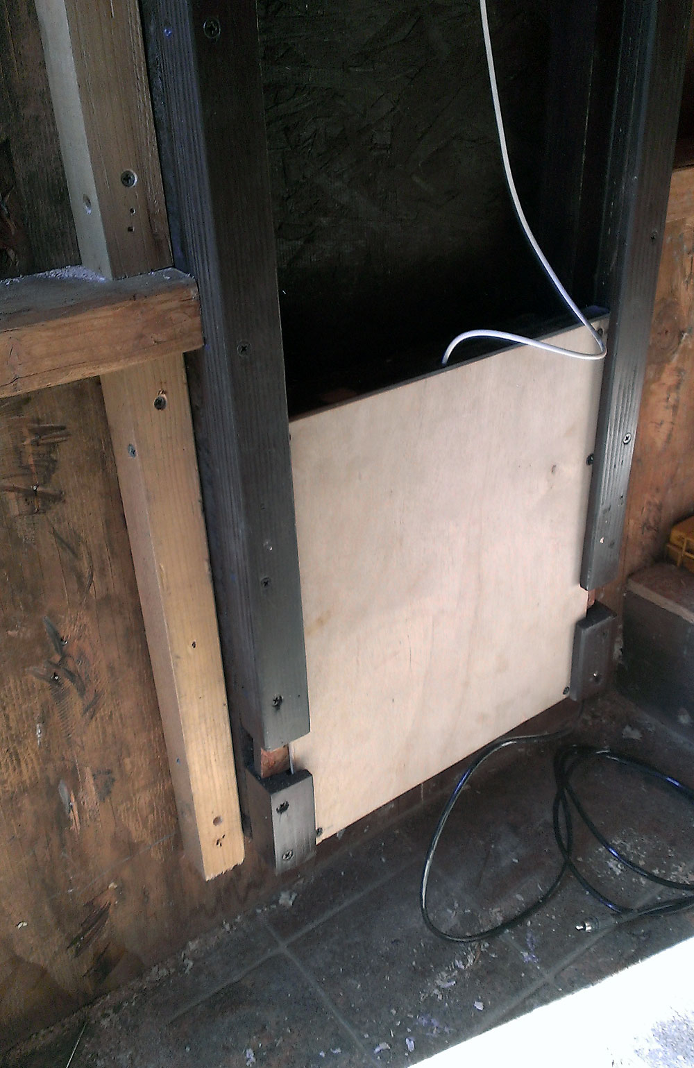
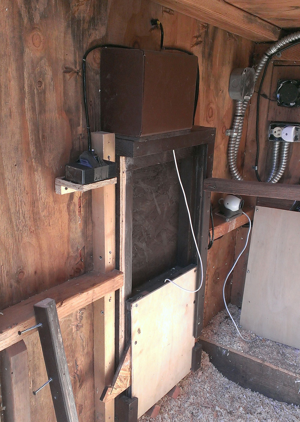

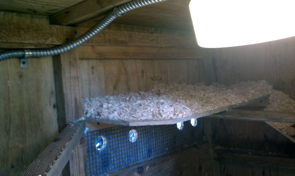
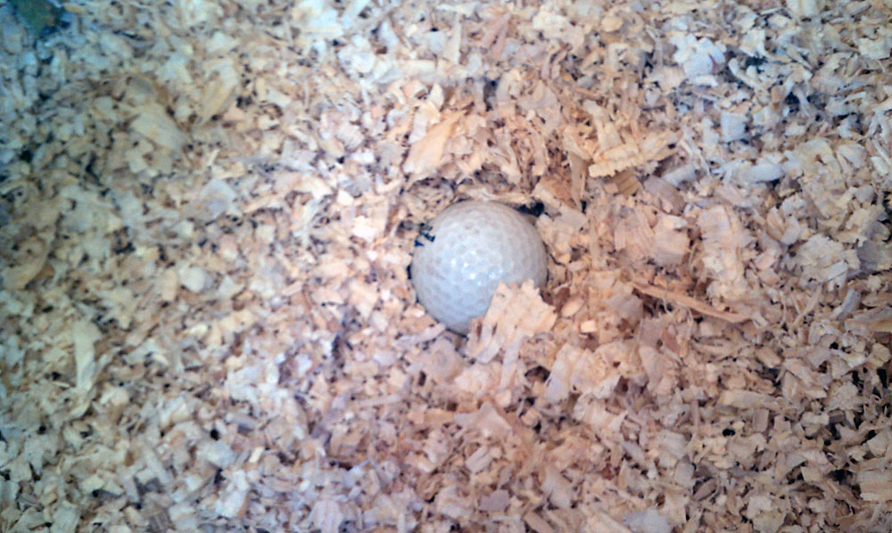

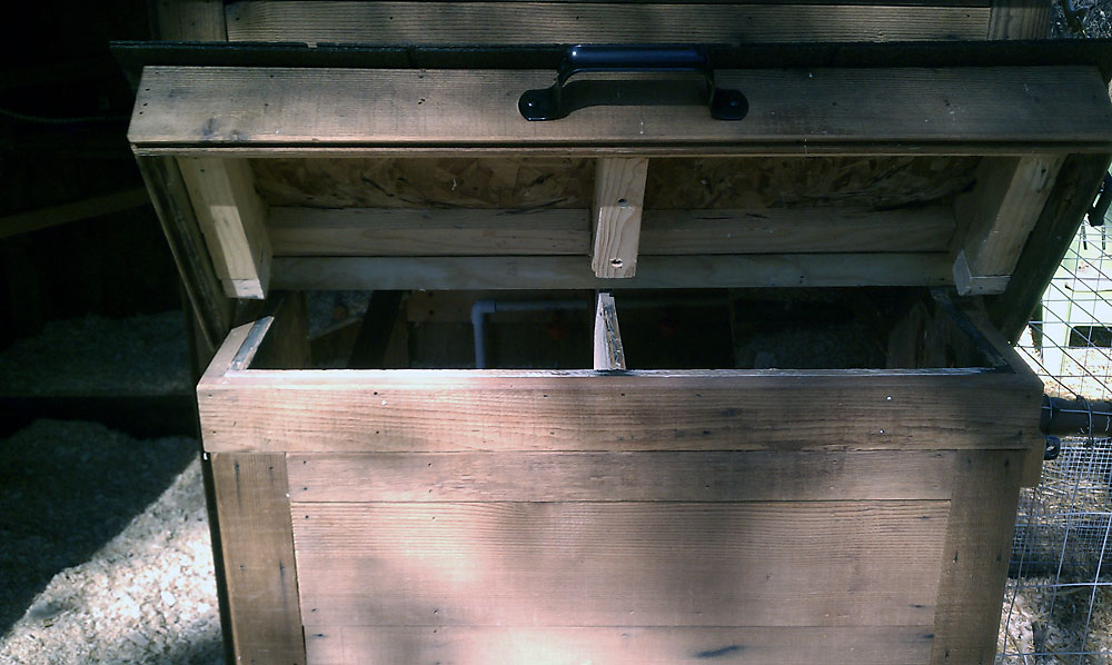
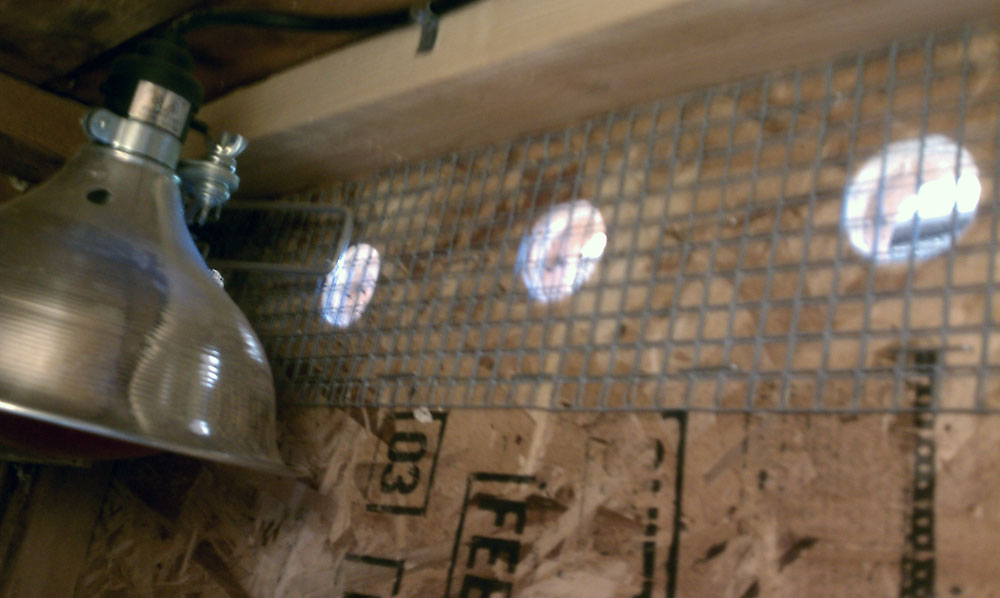
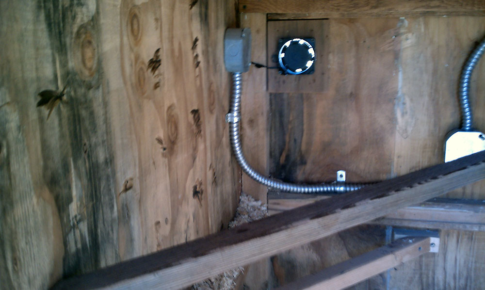
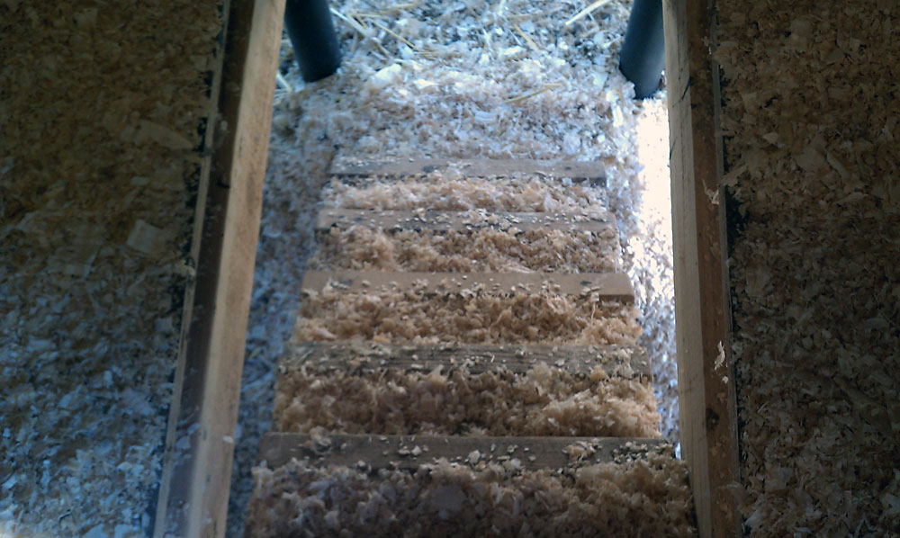
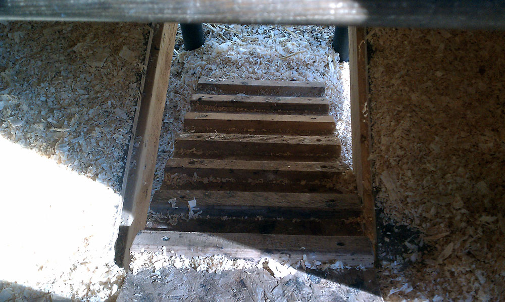
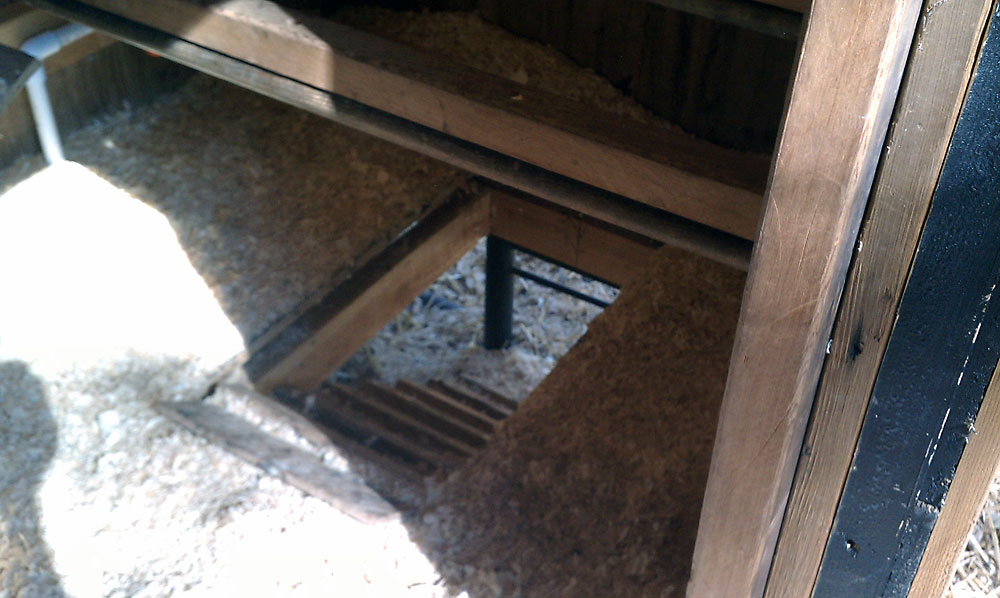


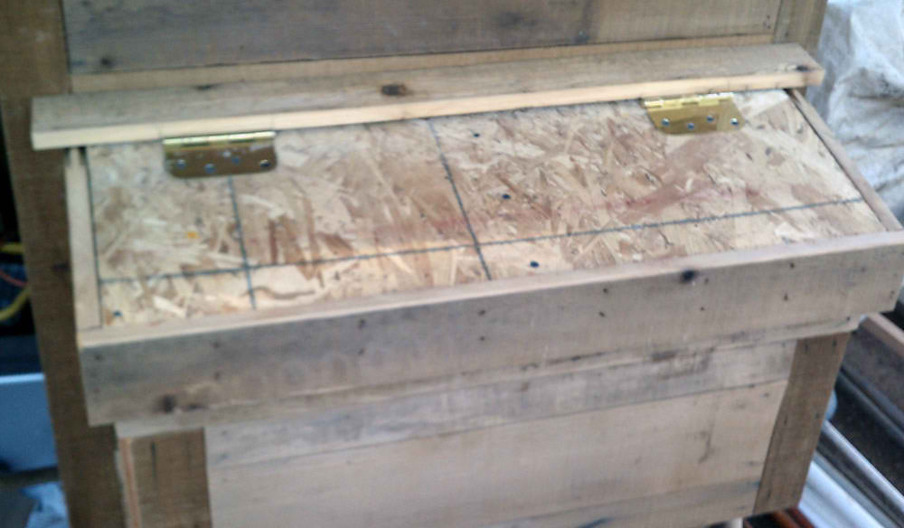
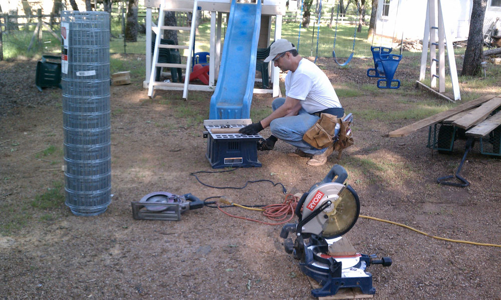
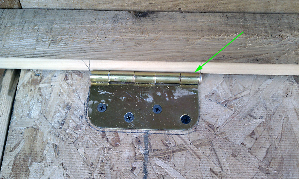
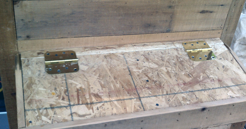
Hello Dave,
constructing your chicken coop door and controller I’m still waitung for some parts…
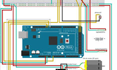
So, having a little time, I tried to make a fritzing from the complete controller, including sensors, LCD and Relais.
The ‘Huehnerino.fzz’ I would like to send you by Email, if there are not perfect things in it, its great if you can change it.
Pictures from door and coop I send further…
Thank you for this great project!
Herbert (Southern Germany, near Lake Constance)
Thank you again, Herbert, for sending me the updated Fritzing diagram and sketch. I’m looking very forward to seeing your pictures of the coop.
Cheers!
Hi Daves.
The whole project is working now for me for about one year..perfectly also with interrior lights.
But now i would like to upgraded the system
I have purchased an ethernet module and i am ready for the next step.
What i want is to build an web server,so i can see remotly all data ( temp,door open or close light on etc etc)…
You think it is posible to do this?My coop is isolated in the middle of a land.
I have all ready bring the internet to the coop ready.
I would appreciated if you have anny suggestion or if you could help me.
Thank you alot.
Pol
Hi Pol… yes, absolutely do-able. I’m planning on the same thing. I found this article in which to help me: https://alexdglover.wordpress.com/2013/02/18/arduino-project-5-internet-control-without-ethernet-shield/ Maybe it can help you as well.
Cheers!
I have code I have written using an Ethernet shied and it works. It you would like a copy I will supply. I have a webpage written that supplies all the variables I used in the code to run the functions that control the coop. I quit trying to do this as it is very easy to cause a lag on pass times. The lags in past times cause great problems to the stability of the door function. The article that Dave refers to is good in that it defers the hosting of a page to a bigger separate system. I think this is very good advise. Experience talking here. I would use TCP for communications to a larger server and send just the data you want in the host server webpage
Mark
i made some progress i found that if i change the 0 to a 1 in this statement it would activate the motor at the correct time but will never shut it off. i know its because ive moved to the trinket but it was SO CHEAP i couldn’t pass it up.
// open the coop door (motor dir open = counter-clockwise)
void openCoopDoorMotorB() {
debounceTopReedSwitch();
// digitalWrite(directionCloseCoopDoorMotorB, LOW); // turn off motor close direction
digitalWrite(directionOpenCoopDoorMotorB, HIGH); // turn on motor open direction
analogWrite(enableCoopDoorMotorB, 255); // enable motor, full speed
// *************this had to be 1 not 0
if (topSwitchPinVal == 1) { // if top reed switch circuit is closed
stopCoopDoorMotorB();
}
}
any idea why i had to change it to a 1. I’m new to this and now i’m confused.
thanks
Ah ha! (normally open vs. normally closed switches) Excellent question…
10 bucks says that your switches were perhaps different than mine and your code then had to be the reverse of mine. (I went through that experience as well) =)
Here’s a quick vid to explain: https://www.youtube.com/watch?v=YN_kV2h-a04
As far as not shutting off, the debounce argument is probably not being invoked (light levels) Meaning, you should make sure your light levels are actually hitting the on/off levels (truly dark or truly light and not anywhere in between) And you have to check to make sure that void openCoopDoorMotorB() and void closeCoopDoorMotorB() are exactly opposite of each other (with the 1 and 0)
//D
Hi Dave I really like what you’ve done with your automatic chicken coop door (so much so that I’m trying to copy it). Ive tried to duplicate it with the code from the instructables web page but am unable to make the door open. I am new to programing so i really am just shooting in the dark.
What I have is a pro trinket 5v https://learn.adafruit.com/introducing-pro-trinket/overview
reed switches from amazon https://www.amazon.com/gp/product/B00PZMG980/ref=oh_aui_detailpage_o06_s00?ie=UTF8&psc=1
photocell https://www.amazon.com/gp/product/B00AFSAOLM/ref=oh_aui_detailpage_o07_s00?ie=UTF8&psc=1
motor controller https://www.amazon.com/gp/product/B00E58EA90/ref=oh_aui_detailpage_o07_s00?ie=UTF8&psc=1
Ive had to change the code for little things like my photocell is backwards from yours for some reason, and of corse i had to change some pins. would you mind looking at the code to see if you can spot why it will not open the door. your code is mostly untouched but im stumped.. thanks
// start code
#include
#include
// libraries
//// libraries
////#include // load the SimpleTimer library to make timers, instead of delays & too many millis statements #include
// load the onewire library/*(before running the sketch, remove spaces before and after the above “>” “<" characters – the instructables editor wouldn't publish the includes unless i added those spaces)
//*/
/*
/* Copyright 2013, David Naves (http://daveworks.net, http://davenaves.com)
*
* This program is free software; you can redistribute it and/or
* modify it under the terms of the GNU General Public License
* as published by the Free Software Foundation; either version 3
* of the License, or (at your option) any later version.
*
* This program is distributed in the hope that it will be useful,
* but WITHOUT ANY WARRANTY; without even the implied warranty of
* MERCHANTABILITY or FITNESS FOR A PARTICULAR PURPOSE. See the
* GNU General Public License for more details.
* *
* You should have received a copy of the GNU General Public License
* along with this program; if not, write to the Free Software
* Foundation, Inc., 51 Franklin Street, Fifth Floor, Boston, MA
* 02110-1301, USA.
*/
/*
* I’m hoping that if you use/modify this code, you will share your
* coop project with me and the world (pictures, whatever)
* I’m big on sharing.
* Cheers,
* //D
*/
//pins
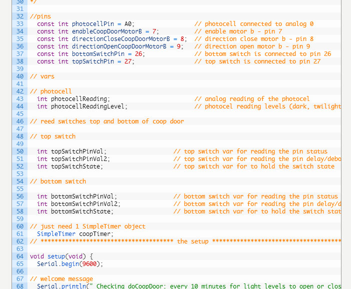
const int photocellPin = A0; // photocell connected to analog 0
const int enableCoopDoorMotorB = 4; // enable motor b – pin 3
const int directionCloseCoopDoorMotorB = 8; // direction close motor b – pin 8
const int directionOpenCoopDoorMotorB = 3; // direction open motor b – pin 11
const int bottomSwitchPin = 0; // rx coop … closed bottom switch is connected to pin rx or 0
const int topSwitchPin = 1; // tx coop …open top switch is connected to pin tx or 1
// vars
// photocell
int photocellReading; // analog reading of the photocel
int photocellReadingLevel; // photocel reading levels (dark, twilight, light)
// reed switches top and bottom of coop door
// top switch
int topSwitchPinVal; // top switch var for reading the pin status
int topSwitchPinVal2; // top switch var for reading the pin delay/debounce status
int topSwitchState; // top switch var for to hold the switch state
// bottom switch
int bottomSwitchPinVal; // bottom switch var for reading the pin status
int bottomSwitchPinVal2; // bottom switch var for reading the pin delay/debounce status
int bottomSwitchState; // bottom switch var for to hold the switch state
// just need 1 SimpleTimer object
SimpleTimer coopTimer;
// ************************************** the setup **************************************
void setup(void) {
Serial.begin(9600);
// welcome message
Serial.println(” Checking doCoopDoor: every 10 minutes for light levels to open or close door”);
Serial.println();
// coop door
// coop door motor
pinMode (enableCoopDoorMotorB, OUTPUT); // enable motor pin = output
pinMode (directionCloseCoopDoorMotorB, OUTPUT); // motor close direction pin = output
pinMode (directionOpenCoopDoorMotorB, OUTPUT); // motor open direction pin = output
// coop door switches
// bottom switch
pinMode(bottomSwitchPin, INPUT); // set bottom switch pin as input
digitalWrite(bottomSwitchPin, HIGH); // activate bottom switch resistor
// top switch
pinMode(topSwitchPin, INPUT); // set top switch pin as input
digitalWrite(topSwitchPin, HIGH); // activate top switch resistor
// timed actions setup
coopTimer.setInterval(1500, readPhotoCell); // read the photocell every second and a half minutes
// coopTimer.setInterval(600000, readPhotoCell); // read the photocell every 10 minutes
}
// functions
// operate the coop door
// photocel to read levels of exterior light
void readPhotoCell() { // function to be called repeatedly – per cooptimer set in setup
photocellReading = analogRead(photocellPin);
Serial.print(” Photocel Analog Reading = “);
Serial.println(photocellReading);
/* original photo cell reading
*
// set photocel threshholds
if (photocellReading >= 0 && photocellReading = 4 && photocellReading = 125 ) {
photocellReadingLevel = ‘3’;
Serial.print(” Photocel Reading Level:”);
Serial.println(” – Light”);
}
*/
// set photocel threshholds im still working to get this working just right but its close
if (photocellReading >= 0 && photocellReading = 350 && photocellReading = 675 ) {
photocellReadingLevel = ‘1’;
Serial.print(” Photocel Reading Level:”);
Serial.println(” – Dark”);
}
}
//debounce bottom reed switch
void debounceBottomReedSwitch() {
//debounce bottom reed switch
bottomSwitchPinVal = digitalRead(bottomSwitchPin); // read input value and store it in val
delay(10);
bottomSwitchPinVal2 = digitalRead(bottomSwitchPin); // read input value again to check or bounce
if (bottomSwitchPinVal == bottomSwitchPinVal2) { // make sure we got 2 consistant readings!
if (bottomSwitchPinVal != bottomSwitchState) { // the switch state has changed!
bottomSwitchState = bottomSwitchPinVal;
}
Serial.print (” Bottom Switch Value: “); // display “Bottom Switch Value:”
Serial.println(digitalRead(bottomSwitchPin)); // display current value of bottom switch;
}
}
// debounce top reed switch
void debounceTopReedSwitch() {
topSwitchPinVal = digitalRead(topSwitchPin); // read input value and store it in val
delay(10);
topSwitchPinVal2 = digitalRead(topSwitchPin); // read input value again to check or bounce
if (topSwitchPinVal == topSwitchPinVal2) { // make sure we got 2 consistant readings!
if (topSwitchPinVal != topSwitchState) { // the button state has changed!
topSwitchState = topSwitchPinVal;
}
Serial.print (” Top Switch Value: “); // display “Bottom Switch Value:”
Serial.println(digitalRead(topSwitchPin)); // display current value of bottom switch;
}
}
// stop the coop door motor
void stopCoopDoorMotorB(){
digitalWrite (directionCloseCoopDoorMotorB, LOW); // turn off motor close direction
digitalWrite (directionOpenCoopDoorMotorB, LOW); // turn on motor open direction
analogWrite (enableCoopDoorMotorB, 0); // enable motor, 0 speed
}
// close the coop door motor (motor dir close = clockwise)
void closeCoopDoorMotorB() {
digitalWrite (directionCloseCoopDoorMotorB, HIGH); // turn on motor close direction
digitalWrite (directionOpenCoopDoorMotorB, LOW); // turn off motor open direction
analogWrite (enableCoopDoorMotorB, 255); // enable motor, full speed
if (bottomSwitchPinVal == 0) { // if bottom reed switch circuit is closed
stopCoopDoorMotorB();
Serial.print(” Coop Door Closed – no danger”);
}
}
// open the coop door (motor dir open = counter-clockwise)
void openCoopDoorMotorB() {
digitalWrite(directionCloseCoopDoorMotorB, LOW); // turn off motor close direction
digitalWrite(directionOpenCoopDoorMotorB, HIGH); // turn on motor open direction
analogWrite(enableCoopDoorMotorB, 255); // enable motor, full speed
if (topSwitchPinVal == 0) { // if top reed switch circuit is closed
stopCoopDoorMotorB();
Serial.print(” Coop Door open – danger! “);
}
}
void doCoopDoor(){
if (photocellReadingLevel == ‘3’) { // if it’s light
if (photocellReadingLevel != ‘2’) { // if it’s not twilight
if (photocellReadingLevel != ‘1’) { // if it’s not dark
debounceTopReedSwitch(); // read and debounce the switches
debounceBottomReedSwitch();
openCoopDoorMotorB(); // Open the door
}
}
}
if (photocellReadingLevel == ‘1’) { // if it’s dark
if (photocellReadingLevel != ‘2’) { // if it’s not twilight
if (photocellReadingLevel != ‘3’) { // if it’s not light
debounceTopReedSwitch(); // read and debounce the switches
debounceBottomReedSwitch();
closeCoopDoorMotorB(); // close the door
}
}
}
}
// ************************************** the loop **************************************
void loop() {
// polling occurs
coopTimer.run();
doCoopDoor();
}
//thanks again for your help
Hi Bo,
Thanks for the comment…
I’m not really familiar with the Pro Trinket but I do see that it’s similar to the Uno.
Few things that first occurred to me to start checking:
– Pin assignments (analog vs. digital / Trinket vs Uno) http://21stdigitalhome.blogspot.com/2014/10/comparing-adafruits-pro-trinket-to.html I have a suspicion that at least part of the problem may be in there.
– What ~exactly~ happens when you tried testing light levels.
– Have you looked at the serial monitor while testing? If so, what exactly did the serial monitor report (I spent a ton of time working out my kinks this way)
Just fyi, as I started building mine out, I did a massive amount of research, and asked tons of very specific questions.
Since you’re using a completely different board, I’d try and track down experts on Pro Trinkets. I’m sure you can find some out on the Arduino Message Boards. https://id.arduino.cc/auth/signup (I’ve spent more than a few hours out there myself) Remember to give as much info as possible in your question (errors, processes followed, etc etc) or your question(s) will most likely be ignored. =)
Hope that helps point you in the right direction.
Cheers,
//D
Hi Dave, I found this works perfectly as a spool, I just added a 1/2 to 5mm nylon spacer and tightened it down:
http://www.amazon.com/Chicago-Die-Single-Grooved-Section/dp/B00GGSYKUG/ref=sr_1_10?ie=UTF8&qid=1434398160&sr=8-10&keywords=chicago+pulley&pebp=1434398258823&perid=A79191BA93594FD8BE37
John
That is KILLER!
Really appreciate the share, John.
Cheers!
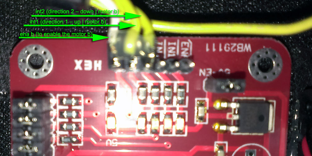
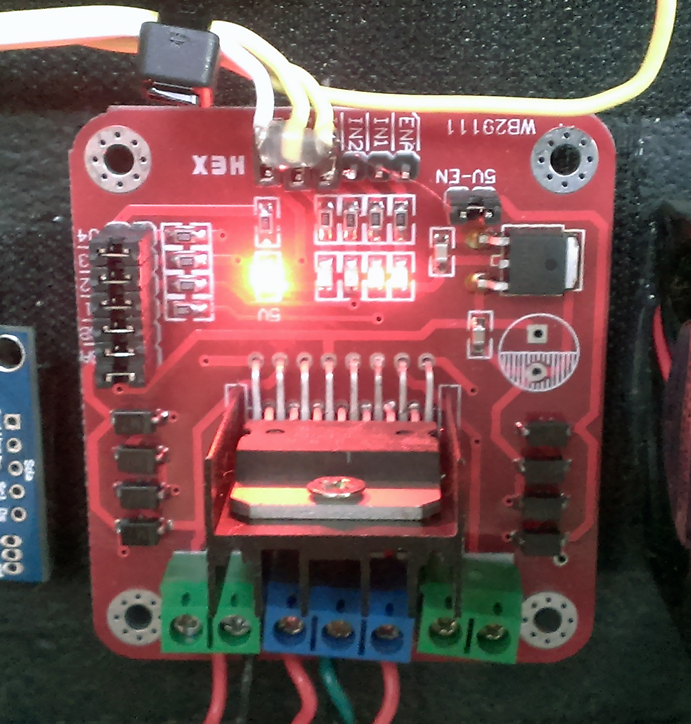
Hi Dave Naves! I’m building (just started) the automatic coop door and I ordered the motor controller l298n. Quick question, in the below photo would you remove the jumper between the 5v and enb then connect the (enab from your fritz) to enb and then (int1 to inc) and (int2 to ind)? And what the heck is this white connector, should I ignore?
Thanks and I’m a big fan of your work!
John
Controller Photo:
https://www.facebook.com/photo.php?fbid=10153424379316060&set=pcb.10153424381806060&type=1&theater
thanks for the notes and the image, john,
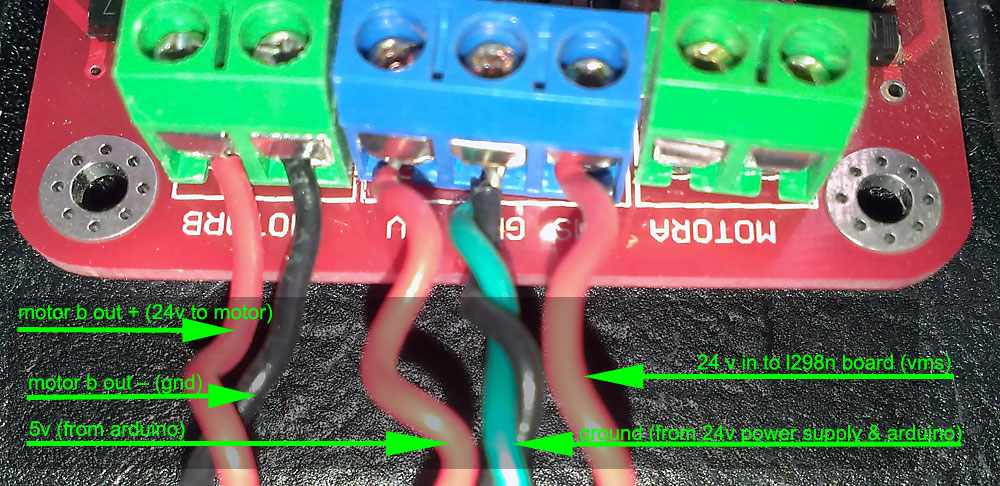
so if you notice the closeup of my motor controller: http://davenaves.com/blog/wp-content/uploads/auto-chicken-door-motor-contoller.jpg
the layout looks a little different than mine, (and i can’t see you your out b/vcc or vms/gnd +5) but it looks like what you need is there.
do this:
pull the jumpers… pretty sure there are 8 posts under there
then hook up:
5v (power from arduino)
gnd (all grounds)
enab (to enable the motor b)
ina (direction 1 – up)
inb (direction 2 – down)
24 v in to l298n board (vms *or* vcc in some controllers)
24v gnd in to l298n board (gnd)
motor b out + (24 volts to motor)
motor b out – (gnd)
yeah, looks like they gave you an additional cable connector end if you had the male end) pretty sure you can ignore
cheers!
Hi Dave, That worked awesomely thanks again! My coop door is automated! One issue I had was when running closeCoopDoorMotorB there was a unsuccessful bottomSwitchPinVal == 0 (lowering blocked by sticky door) and the pulley kept winding until it raised the door again, because of a wrap around. I think we should add:
Pseudo code:
Lower door
wait 1 second
check for top switch == 0 (possible wrap around)
attempt to lower again (right away)
check for bottomswitch ==0 (successfully closed)
Thoughts?
Thanks
John
Sorry for the late reply… just noticed this comment.
I like it! (I could’ve used this when I was wrangling with the debouncing and couldn’t figure out that the sun doesn’t think about throwing perfect light reading ranges within millis) =^ )
When I have more time, I’ll write something up… or were you thinking of doing this yourself?
Cheers and thanks!
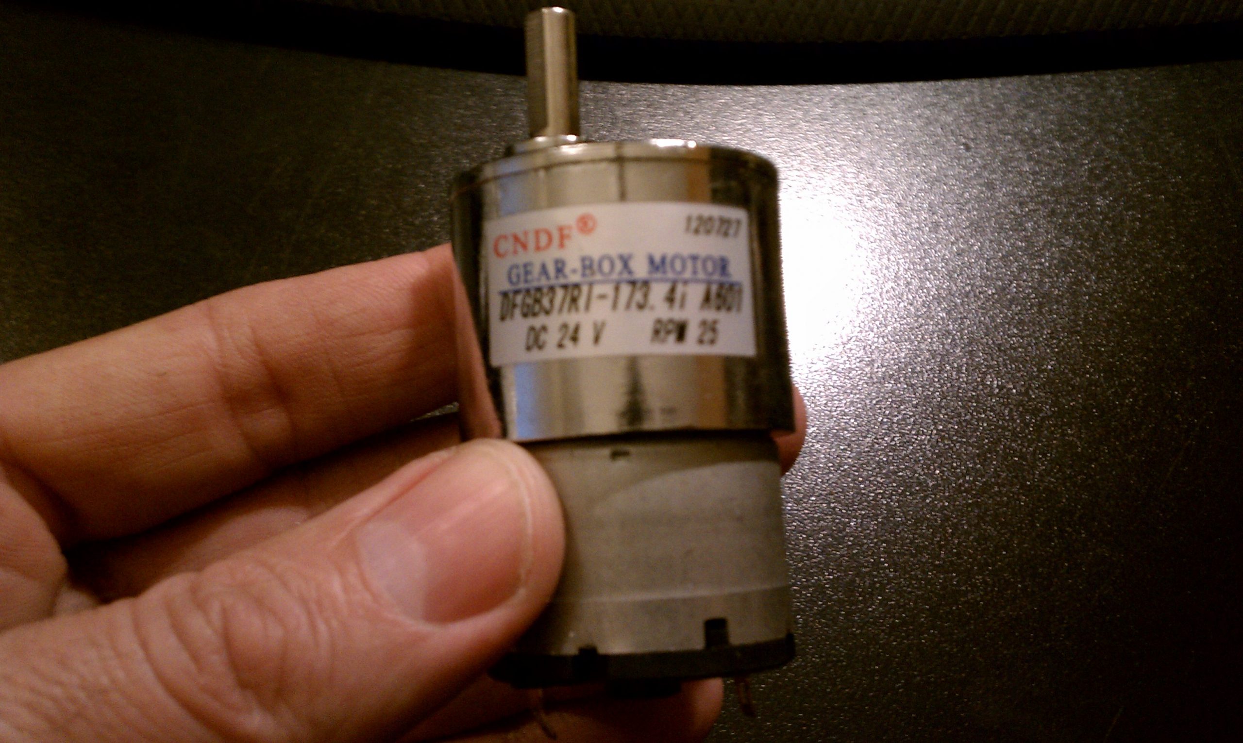
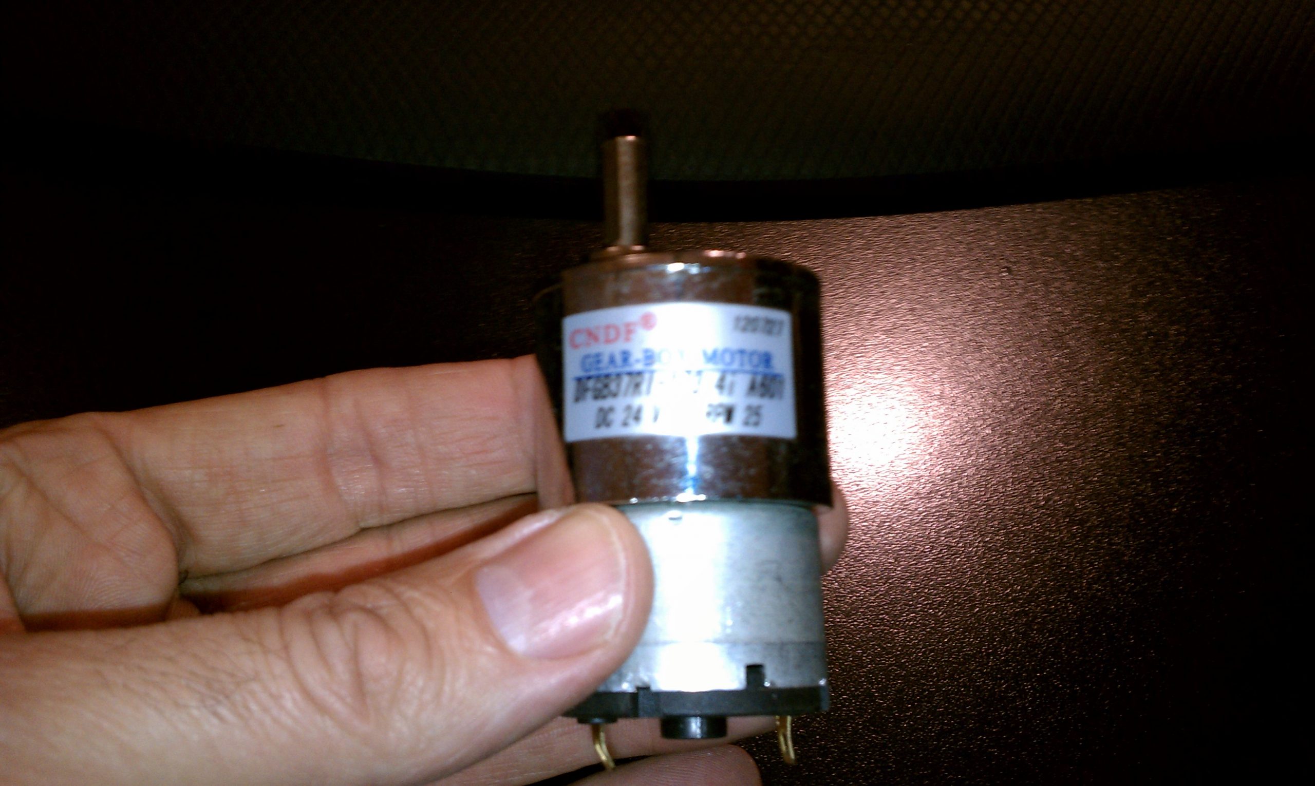
I am trying to make a chicken coop similar to yours but I would like to use a 12 volt motor for the door do you have any suggestions? Also how much torque does your 24 volt motor have.
hi david,
thanks for the question… ya know the motor i purchased didn’t indicate the torque, but i did a quick search for you, and this one should do just fine: http://amzn.to/1E3Z3dR (my aff link) the important thing to remember is to not get a motor that spins too fast and that your spool isn’t too large in diameter. (too large makes it hard on the motor)
btw, the only reason i used 24v was b/c i already had 120v down at the coop and was being overly cautious.
good luck and post some pics so we can see your project!
cheers,
//d
I love your chicken coop controller. It has inspired me in making a coop and controller for my Son and Daughter in law.
I have a few videos of the coop, controller, and development system. I am not done with the run code yet. Please view if you have time.
I am new to making videos,
https://www.youtube.com/watch?v=VadxzVbJdhw
https://www.youtube.com/watch?v=89n0P67-vK8
https://www.youtube.com/watch?v=n-wSwi32VxI
I am mounting the controller panel in Bud box in the rear
Mark,
You are the MAN! Love your whole custom setup. (and I’m especially loving the cable management!)
Really appreciate you sharing with us!
Cheers,
//D
This is the best robo-chicken coup I’ve seen. Love the door lock and the predator deterrent. The control panel is nicely done. This web site is pretty awesome as well. Something that conveyors the eggs directly to the fry pan in the morning would be a great add.
Hey thanks, Paul! Really appreciate the kind words. You’re right.. Arduino-based egg conveyor belt to frying pan… there’s something there!
Cheers,
//D